
Datasheet


VLMW51Q2R3
www.vishay.com
Vishay Semiconductors
Rev. 1.0, 16-May-13
1
Document Number: 84160
For technical questions, contact: LED@vishay.com
THIS DOCUMENT IS SUBJECT TO CHANGE WITHOUT NOTICE. THE PRODUCTS DESCRIBED HEREIN AND THIS DOCUMENT
ARE SUBJECT TO SPECIFIC DISCLAIMERS, SET FORTH AT www.vishay.com/doc?91000
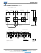
Power SMD LED PLCC-2 Plus
DESCRIPTION
The VLMW51.. white LED in PLCC-2 plus package is an
advanced product in terms of high luminous flux and low
thermal resistance.
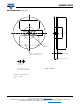
In combination with the small package outline (3.5 mm x
3.5 mm x 1.2 mm) the PLCC-2 plus is an ideal choice for
backlighting, signage, exterior and interior automotive
lighting as well as all general lighting applications.
PRODUCT GROUP AND PACKAGE DATA
• Product group: LED
• Package: SMD PLCC-2 plus
• Product series: power
• Angle of half intensity: ± 60°
FEATURES
• High efficient InGaN technology
• Long life, due to silicone resin casting
• Compact package outline 3.5 mm x 3.5 mm x
1.2 mm
• Angle of half intensity = ± 60°
• Luminous flux and color categorized per
packing unit
• Luminous flux ratio per packing unit
max.
/
min.
< 1.2
• ESD-withstand voltage: up to 2 kV (HBM)
according to JESD22-A114-B
• Preconditioning according to JEDEC level 2a
• Compatible with IR-reflow soldering profiles according to
J-STD-020
• AEC-Q101 qualified
• Material categorization: For definitions of compliance
please see www.vishay.com/doc?99912
APPLICATIONS
• Camera flash light
•Marker lights
• Interior and exterior automotive lighting
• Decorative lighting
• Architectural lighting
• All kinds of general lighting
• Backlighting (TFT LCD displays)
Note
• Not designed for reverse bias
22038
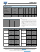
PARTS TABLE
PART COLOR
LUMINOUS FLUX
(mlm)
at I
F
(mA)
COORDINATE
(x, y)
at I
F
(mA)
FORWARD VOLTAGE
(V)
at I
F
(mA)
TECHNOLOGY
MIN. TYP. MAX. MIN. TYP. MAX. MIN. TYP. MAX.
VLMW51Q2R3-GS08 White 30 600 40 000 51 700 150 -
0.33,
0.33
- 150 3 3.4 4.1 150 InGaN
ABSOLUTE MAXIMUM RATINGS (T
amb
= 25 °C, unless otherwise specified)
VLMW51Q2R3
PARAMETER TEST CONDITION SYMBOL VALUE UNIT
DC Forward current I
F
180 mA
Surge forward current t
p
10 μs I
FSM
350 mA
Power dissipation PV 738 mW
Junction temperature T
jmax.
125 °C
Operating temperature range T
amb
- 40 to + 100 °C
Storage temperature range T
stg
- 40 to + 100 °C
Thermal resistance junction/solder point R
thJS
45 K/W
Thermal resistance junction/ambient Mounted on PC board total Cu area > 900 mm
2
R
thJA
125 K/W