Assembly & Owner’s Guide ST730 MULTI-LAT
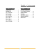
Table of Contents A S S E M B LY G U I D E OWNER’S GUIDE ASSEMBLY GUIDE . . . . . . . . . . . . . . . . 4 HARDWARE BAGS . . . . . . . . . . . . . . . . 6 STEP 1: ORANGE BAG . . . . . . . . . . . . . 9 STEP 2: BLUE BAG . . . . . . . . . . . . . . . 10 STEP 3: PINK BAG . . . . . . . . . . . . . . . 11 STEP 4: GREEN BAG . . . . . . . . . . . . . . 12 STEP 5: CABLE #1 . . . . . . . . . . . . . . . 13 STEP 6: CABLE #2 . . . . . . . . . . . . . . . 14 STEP 7: BLACK BAG . . . . . . . . . . . . . .
Assembly & Owner’s Guide ST730 MULTI-LAT To avoid possible damage to this Multi-Lat, please follow these assembly steps in the correct order. Before proceeding, find your new Multi-Lat serial number located on the side of the main floor support (AT1), and enter here: Refer to this number when calling for service, and enter this serial number on your Warranty Card and in your own records. Be sure to read your Owner’s Guide before using your new Multi-Lat.
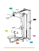
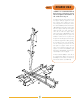
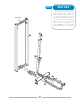
STEP 4 General Warning Decal STEP 5 STEP STEP STEP 7 6 8 STEP Serial # STEP STEP 1 5 2 3
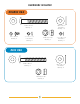
HARDWARE INCLUDED ORANGE BAG M10 x 72 Bolt Quantity: 7 M5 x 10 Bolt Quantity: 4 10.2 x 22 x 2 Flat Washer Quantity: 14 5.1 x 9.3 x 1.3 Lock Washer Quantity: 4 M10 Nylon Nut Quantity: 7 5.3 x 10 x 1.0 Flat Washer Quantity: 4 BLUE BAG M10 x 70 Bolt Quantity: 2 10.
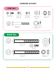
HARDWARE INCLUDED PINK BAG M5 x 10 Bolt Quantity: 20 5.3 x 10 x 1.0 Flat Washer Quantity: 20 5.1 x 9.3 x 1.3 Lock Washer Quantity: 20 M8 x 62 Bolt Quantity: 2 8.4 x 15.5 x 1.6 Flat Washer Quantity: 4 M8 Nylon Nut Quantity: 2 Stopper Ring (illustration not to scale) Quantity: 1 GREEN BAG M10 x 95 Bolt Quantity: 2 10.
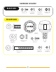
HARDWARE INCLUDED BLACK BAG 5.1 x 9.3 x 1.3 Lock Washer Quantity: 4 M5 x 10 Bolt Quantity: 36 5.3 x 10 x 1 Flat Washer Quantity: 20 M5 Nylon Nut Quantity: 2 YELLOW BAG M10 x 25 Bolt Quantity: 6 Pull Pin Quantity: 1 10.2 x 22 x 2 Flat Washer Quantity: 2 M10 Nylon Nut Quantity: 1 M5 x 15 Bolt Quantity: 4 5.3 x 10 x 1 Flat Washer Quantity: 4 M10 x 75 Bolt Quantity: 1 8 5.1 x 9.3 x 1.
STEP 1 ORANGE BAG • NOTE: It is recommended that all bolts in Steps 1 thru 4 are loosely fastened. Tighten all hardware at the conclusion of Step 4 • With the flat side down, place the left foot support (AT2) up against the main floor support (AT1), aligning the three holes along bottom of both pieces. Place three bolts (M10x72) and three flat washers (10.2x22x2) through left foot support and main floor support.
STEP 2 BLUE BAG • With the weight stack tower (AB1) standing upright, slide it against the T-shaped bracket at the end of the main floor support (AT1) (with the “Front” sticker facing the rest of the machine). Line up the holes at the bottom of the weight stack tower with the holes in the main floor support. Secure the connection with two bolts (M10x70), four flat washers (10.2x22x2), and two nylon nuts (M10).
STEP 3 PINK BAG • Secure top and bottom shield brackets (B10) to weight stack tower using bolts (M5x10), lock washers (5.1x9.3x1.3), and flat washers (5.3x10x1.0) provided. Repeat for all side brackets (BO9). B10 • Place two rubber weight plate bumpers (Z25) over the holes in the lower cross tube of the weight stack tower. With the horizontal holes of the guide rods at the top, place the guide rods (KO5) over and through the rubber weight plate bumpers into the weight stack tower (AB1).
STEP AF2 AC2 AB1 AG1 12 4 GREEN BAG • Attach the bearing tubes (AF2) to the overhead lat arm (AC2) with four bolts (M6x15). • Lift the overhead lat arm (AC2) and set atop the upright frame (AG1) and the brackets in the weight stack tower (AB1). Slide two bolts (M10x98) with two flat washers (10.2x22x2) up through each bracket on weight stack tower and secure with two flat washers (10.2x22x2) and two nylon nuts (M10).
STEP F D G K AF2 H I B AF1 A F17 E 13 CABLE #1 • Remove pulley A from the left overhead pulley bracket (AF2) and guide one end of cable #1 (F17) through housing on the bracket. Reinstall pulley, making sure cable is between pulley and small roller in front of the bracket. Guide the cable along the overhead arm, through pulleys B, C, and D. Remove pulley E from weight stack pulley bracket, reinstalling after guiding the cable through.
STEP 6 CABLE #2 • Remove pulley M and one of the rollers (GO9) in the front of the upright frame (AG1). Guide the bolt end of cable #2 (F18) through the hole, routing towards the rear in upright frame (AG1), and reinstall roller (G09) and pulley M for the cable to wrap around (bottom). Remove the bottom pulley (L) on the floating tri-pulley (AF1), place the cable (F18) inside, and reinstall pulley.
STEP BLACK BAG 7 • Loosely attach each of the two shield mounting brackets (B11) to the underside of the overhead lat arm (AC2) with two bolts (M5x10), two lock washers (5.1x9.3x1.3), and two flat washers (5.3x10x1) Q06 • Align holes in rear shield (QO3) with the holes in the brackets (BO9 & B11) on the back side of the weight stack; loosely secure using 8 bolts (M5x10).
STEP 8 YELLOW BAG • Slide the thigh support post (AT4) into the seat support opening (AT1). Thread pull pin (T17) into hole on the front of the seat support (AT1) until it latches into place. • Mount the seat onto the seat support using six bolts (M10x25). • Attach the two bar storage snap hooks (B14) to the side of the weight stack tower (AB1) with four bolts (M5x15), four spring washers (5.1x9.3x1.3), and four flat washers (5.3x10x1).
RESISTANCE TRAINING BENEFITS AND TIPS Always consult a physician before starting an exercise program. To be successful in your exercise program, it is important to develop an understanding of the basic principles of resistance training. Now that you have assembled your VISION FITNESS gym, it is only natural that you want to get started immediately. First, determine a few realistic, short term goals and expectations for yourself. Choose an appropriate exercise routine that best suits your individual needs.
TRAINING PROGRAMS MUSCULAR ENDURANCE A program that stresses moderate intensity, a lower amount of resistance, and higher repetitions (anywhere from 13-100 or more). These types of sets will take longer to complete. This type of training conditions the muscles for activities that stress the slow twitch muscle fibers of your body. This is beneficial for sustaining energy over moderate periods of time.
STRETCHING Flexibility Training is not associated with fitness as often as cardiovascular exercise or Strength Training, even though it is just as important. A good stretching program will help to maintain flexibility of the hips and lower back. A flexible person will be less likely to injure themselves in common activities, such as reaching, twisting and turning, or in uncommon activities such as the annual softball tournament.
BICEP/CHEST STRETCH Grasp an immovable object (pole or corner of a wall) with your feet planted firmly and evenly on the floor. With the palm of your stretched side facing forward, rotate your hips away from that hand. Be careful not to rotate too far or hyperextend the elbow joint. Hold the stretch for 15 to 30 seconds. Repeat with the opposite side, and continue to alternate as necessary. TRICEP STRETCH Stand erect with your eyes fixated straight ahead.
MAINTENANCE SCHEDULE FOR BEST PERFORMANCE WE RECOMMEND THE FOLLOWING MAINTENANCE SCHEDULE: Check the integrity and function of the following parts. Replace all worn components immediately. ITEM DAILY WEEKLY • • • • • • • • CABLES CHECK END FITTINGS AND CABLE JACKET COATING. CHECK TIGHTNESS OF WEIGHT STACK LOCKING NUT. REPLACE CABLES ANNUALLY. UPHOLSTERY WIPE DOWN AND DRY. CLEAN AND CONDITION. FRAME WIPE WITH WATER DAMPENED CLOTH AND DRY COMPLETELY. POLISH AND WAX.
ST730 COMMERCIAL WARRANTY* COMMERCIAL USES DEFINED VISION FITNESS warrants the ST730 model Multi-Lat for use in commercial facilities. Examples of commercial facilities include but are not limited to: Hotels; Resorts; Police and Fire Stations; Apartment Complexes; Rehabilitation and Sports Medicine Clinics; Hospitals; Elementary, Middle, and High Schools; YMCAs; Private Health Clubs; Colleges and Universities.
it all starts with a vision 500 South CP Avenue • P.O. Box 280 • Lake Mills. WI 53551 toll free 800.335.4348 • phone 920.648.4090 • fax 920.648.3373 www.visionfitness.com ©2006 Vision Fitness. All Rights Reserved. 11.06 OM18.