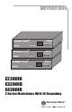
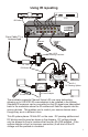
TM E Series CHANNEL VISION Down Up Select A B C D E4200IR TM E Series CHANNEL VISION Down Up Select A B C E3200IR TM E Series CHANNEL VISION Down Up Select E2200IR A B E2200IR E3200IR E4200IR E Series Modulators With IR Repeating
The E2200IR, E3200IR, & E4200IR are 2, 3, & 4-input RF modulators that create user selectable TV channels from standard composite video signals. In addition to creating a whole-house audio video system, these units also provide an integrated IR repeating system that runs over the same coax that delivers video to your TV set. Features: ! LED display for easy setup ! 25dBmV output ! Integrated IR engine creates a coax-based IR system ! IR emitter outputs ! Simple installation and setup LED Display...
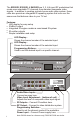
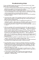
Basic Setup CABLE ANTENNA D B 12 3 4 OUTPUT IR RF OUT C A L AUDIO R VIDEO L AUDIO R VIDEO ANTENNA + CABLE OUTPUT IR 1 2 3 4 DC 15V IN Dip Switch Settings Remove power before changing switch settings. Cable settings... channels 65-135 Switches 1, 2, & 4 are down, switch 3 is up. Use this setting if the modulator will be installed on a 1 2 3 4 system that is distributing cable TV. 1 2 3 4 1 2 3 4 Antenna settings... channels 14-78 Switches 1 and 2 are up, switches 3 and 4 are down.
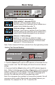
Basic Application Sat Receiver VCR B D A C CABLE ANTENNA 12 3 4 OUTPUT IR L AUDIO R RF OUT VIDEO From Cable TV or Antenna feed Camera L AUDIO R ANTENNA + CABLE OUTPUT IR VIDEO 1 2 3 4 DC 15V IN Camera HS-2 Combiner IN/out TM IN/out OUT/in OUT/in 5MHz-1GHz All Port DC passing Part No. HS-4 4-WAY SPLITTER/COMBINER CHANNEL VISION OUT/in TM OUT/in OUT/in CHANNEL VISION 5MHz-1GHz All Port DC passing Part No.
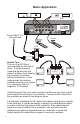
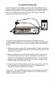
Using IR repeating Sat Receiver VCR IR Emitter B D A C CABLE ANTENNA 12 3 4 OUTPUT IR L AUDIO R RF OUT VIDEO From Cable TV or Antenna feed Camera L AUDIO R ANTENNA + CABLE OUTPUT IR VIDEO 1 2 3 4 DC 15V IN Camera IN/out TM OUT/in CHANNEL VISION 5MHz-1GHz All Port DC passing Part No. HS-2 2-WAY SPLITTER/COMBINER OUT/in HS-2 DC Passing Combiner RF Filter DC Blocks IN/out OUT/in OUT/in 5MHz-1GHz All Port DC passing Part No.
Troubleshooting Video If your modulated signal looks ‘snowy’ or if you don’t see it at all, follow these steps to correct the problem. 1. If you are combining the modulator with the an antenna or CATV signal (as shown on pages 4 & 5) disconnect the antenna or CATV signal so that the modulator is the only signal in the system. a.
Troubleshooting IR If your IR system is not working, check to see if the modulator’s IR engine is feeding approximately 12 Volts DC onto the coax between the shield and center pin. (Any voltage between 8-12VDC is OK). If there is no voltage between the center pin and shield, check the connectors on each end of the coax.
Specifications RF Modulator Video Audio RF Carriers Freq. Stability Freq. Range PLL Synthesized Oscillator NTSC L&R summed Monaural Spurious Output Rejection Outside Carrier +12MHz >70dBC Inside Carrier +12MHz >55dBC Isolation Greater than 70dB +50kHz Inputs UHF 471.25-855.25MHz Video 0.4V-2.7Vpp adjustable Ultraband 469.25-859.25MHz Audio 1V RMS Channels UHF 14-78, Ultraband 65-135 Connectors (Excluding 95-99) Video Inputs RCA Female Channel Width 6.0MHz Audio Inputs RCA Female Audio Offset 4.