
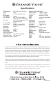
Specifications

RF OUTRF OUT
DC 15V INDC 15V IN
OUTPUT
IR
OUTPUT
IR
CABLECABLE
ANTENNAANTENNA
ANTENNA + CABLEANTENNA + CABLE
VIDEOVIDEO
AUDIOAUDIO
L RL R
BB
AA
VIDEOVIDEO
AUDIOAUDIO
L RL R
DD
CC
11
44
33
22
1122
33
44
OUTPUT
IR
OUTPUT
IR
RF OUTRF OUT
DC 15V INDC 15V IN
OUTPUT
IR
OUTPUT
IR
CABLECABLE
ANTENNAANTENNA
ANTENNA + CABLEANTENNA + CABLE
VIDEOVIDEO
AUDIOAUDIO
L RL R
BB
AA
VIDEOVIDEO
AUDIOAUDIO
L RL R
DD
CC
11
44
33
22
1122
33
44
OUTPUT
IR
OUTPUT
IR
TM
C H A N N E L VI S I O N
TM
C H A N N E L VI S I O N
E 4 2 0 0 I RE 4 2 0 0 I R
AA
BB
CC
DD
E S e r i e sE S e r i e s
Do w nDo w n
UpUp
Se l ectSe l ect
T M
C H A N N E L VI S I O N
T M
C H A N N E L VI S I O N
E 4 2 0 0 I RE 4 2 0 0 I R
AA
BB
CC
DD
E S e r i e sE S e r i e s
Do w nDo w n
UpUp
Se l ectSe l ect
2
3
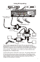
The E2200IR, E3200IR, & E4200IR are 2, 3, & 4-input RF modulators that
create user selectable TV channels from standard composite video
signals. In addition to creating a whole-house audio video system, these
units also provide an integrated IR repeating system that runs over the
same coax that delivers video to your TV set.
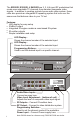
Dip Switch Settings
Remove power before changing switch settings.
Setting The Channel Number
Note: Cable channels 95-99 are excluded from all programming modes
Note: Do not program the modulator to consecutive channels, this will
cause poor picture quality. Skip at least one channel between your
selections. For example: 65, 67, 69, 71 would be OK.
1 2
Cable settings... channels 65-135
Switches 1, 2, & 4 are down, switch 3 is up.
Use this setting if the modulator will be installed on a
system that is distributing cable TV.
Antenna settings... channels 14-78
Switches 1 and 2 are up, switches 3 and 4 are down.
Use this setting if the modulator will be installed on a
system that is distributing signals from an antenna.
Antenna + Cable settings...
Switches 1,2, and 3 are up, switch 4 is down.
This is rarely used, but it allows the modulator to be
programmed to antenna channels 14-39 and cable
channels 91-135 simultaneously.
1. Press the Select button until the LED indicator is illuminated for the
input you wish to set. The LED display will show the current channel
setting.
2. Press and hold the Select button until the LED indicator begins to
blink. While it is blinking press the Up or Down button until the desired
channel is shown in the LED display. Press the Select button again to
set then next input to a new channel. If no button is pressed for 2
seconds, the modulator will exit the programming mode.
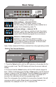
Programming Buttons...
Used to set the desired input to a specific channel..
LED Display...
Shows the channel number of the selected input.
LED Display...
Shows the channel number of the selected input.
IR Outputs... Connect IR emitters here.
Video Level Adjustment... (bottom of unit)
Adjusts the level of composite video input signal.
Audio/Video Inputs...
Connect sources here.
Programming Switches...
Used to set the channel mode of the modulator.
RF Output... Connect to video distribution system.
Power Input... Connect Power supply here.
Note: E4200 shown for reference only, E2200 & E3200 are similar.
Features:
!
LED display for easy setup
!
25dBmV output
!
Integrated IR engine creates a coax-based IR system
!
IR emitter outputs
!
Simple installation and setup
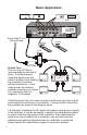
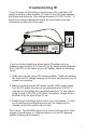
Basic Setup
11
44
33
22
11
44
33
22
11
44
33
22