I T I S H I G H LY R E C O M M E N D E D T H A T T H E I N S T R U C T I O N S B E R E A D T H R O U G H B E F O R E I N S T A L L A T I O N . MILANO 200 DOUBLE DOOR RETRACTABLE SCREEN DOOR INSTALLATION INSTRUCTIONS INSTALLATION TOOLS PHILLIPS SCREWDRIVER MEASURING TAPE HAND-HELD OR POWER SAW POWER DRILL & BITS Use saw blade suitable for cutting aluminum.
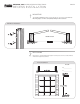
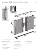
MILANO 200 RECESS INSTALLATION U PULL BAR Q Q O C PA G E 2 Optional Bottom Slide Bolt P P B O Q Q I I C I I K PULL BAR K S S I H Optional Top Slide Bolt A J K I H I K G A G K R I R H I I K I B I E F PART DESIGNATIONS F Threshold Transition End Caps (optional, ordered separately) A Screen Cassette Assembly G Handle B Bottom Guide Rail C Top Guide Rail H Recess Mount Clips I #8 x 3/4”(19mm) Phillips E Threshold Transition (optional, ordered separately)
M ILANO 200 IN STA LL ATIO N IN S T R U C T ION S PA G E 3 RECESS INSTALLATION 1 MOUNTING The A-Screen Cassettes will be mounted inside the door frame using H-Recess Mounting Clips and I-#8 x 3/4”(19mm) Phillips Panhead Screws. 1-A Recess Installation I H Double Screen A I H 2 MEASURING Measure the opening width and height in several places and record the smallest width and height measurement.
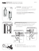
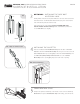
M ILANO 200 IN STA LL ATIO N IN S T R U C T ION S PA G E 4 RECESS INSTALLATION O 3.1 TOP 3 OPTIONAL • INSTALLING THE SLIDE BOLT ACCESSORY LOCK Identify which of the two screen panels will be the one most often used to enter and exit the home. You will install the Slide Bolt Accessory Lock on the interior PULL BAR side of this inactive panel (the side less used). In the interior groove of the pull bar, slide in an S-Slide Bolt at the bottom and then another at the top.
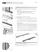
M ILANO 200 IN STA LL ATIO N IN S T R U C T ION S PA G E 5 RECESS INSTALLATION 6.1 6 INSTALLING THE TOP AND BOTTOM GUIDE RAILS Slide the B-Bottom Guide Rail fully onto the tab on the A-Screen Cassette End Cap [6.1]. Repeat for the C-Top Guide Rail [6.2]. On the opposite end of the top and bottom guide rails, insert the tabs of the second Cassette.Move the Cassette and guide rails into position within the door opening then clip the second Cassette into the Recess Mounting Clips.
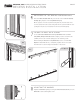
M ILANO 200 IN STA LL ATIO N IN S T R U C T ION S RECESS INSTALLATION 9.1 PULL BAR O 9 PA G E 6 OPTIONAL • INSTALLING SLIDE BOLT RETAINERS (APPLICABLE ONLY IF STEP FOUR WAS IMPLEMENTED) Close the screen doors. Now, on the B-Bottom Guide Rail and the C-Top Guide Rail, make pencil marks to the center of the channel in which you’ve installed the Slide Bolts. Center the P-Slide Bolt Retainer to your channel mark, with the bottom of the Retainer flush to the bottom of the B-Bottom Guide Rail.
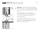
MILANO 200 SURFACE INSTALLATION U PULL BAR Q Q O C PA G E 7 Optional Bottom Slide Bolt P P B O Q M Q C M K M I K L PULL BAR Optional Top Slide Bolt A J L K I I K G A G L K K I M B M PART DESIGNATIONS A Screen Cassette Assembly J Pile / Weather Strip B Bottom Guide Rail K Rubber Bumpers C Top Guide Rail L Surface Mount Clips G Handle M 1/8”(3mm) x 1-3/4”(44mm) Surface Mount Screwsl I #8 x 3/4”(19mm) Phillips Panhead Screws O Slide Bolts P Slide Bolt R
M ILANO 200 IN STA LL ATIO N IN S T R U C T ION S PA G E 8 SURFACE INSTALLATION 1 MOUNTING Surface / Flush Mount the A-Screen Cassette using L-Surface Mounting Clips and I-#8 x 3/4”(19mm) Phillips Panhead Screws. Surface Installation Door L I Jamb A L I Brickmold 2 MEASURING Measure the opening width and height in several places and record the smallest width and height measurement.
M ILANO 200 IN STA LL ATIO N IN S T R U C T ION S SURFACE INSTALLATION O 3.1 TOP 3 PA G E 9 OPTIONAL • INSTALLING THE SLIDE BOLT ACCESSORY LOCK Identify which of the two screen panels will be the one most often used to enter and exit the home. You will install the Slide Bolt Accessory Lock on the interior PULL BAR side of this inactive panel (the side less used). In the interior groove of the pull bar, slide in an S-Slide Bolt at the bottom and then another at the top.
M ILANO 200 IN STA LL ATIO N IN S T R U C T ION S PA G E 1 0 SURFACE INSTALLATION 6.1 A 6 INSTALLING THE TOP AND BOTTOM GUIDE RAILS Slide the B-Bottom Guide Rail fully onto the tabs on the A-Screen Cassette End Cap [6.1]. NOTE: The Bottom and Top Rails each have decorative grooves on one side. This groove should face the outside [6.2]. B Slide the C-Top Guide Rail onto the tabs of the A-Screen Cassettes Assembly [6.3]. 6.
M ILANO 200 IN STA LL ATIO N IN S T R U C T ION S SURFACE INSTALLATION 9.1 PULL BAR O 9 PA G E 1 1 OPTIONAL • INSTALLING SLIDE BOLT RETAINERS (APPLICABLE ONLY IF STEP FOUR WAS IMPLEMENTED) Close the screen doors. Now, on the B-Bottom Guide Rail and the C-Top Guide Rail, make pencil marks to the center of the channel in which you’ve installed the Slide Bolts. Center the P-Slide Bolt Retainer to your channel mark, with the bottom of the Retainer flush to the bottom of the B-Bottom Guide Rail.
M ILANO 200 IN STA LL ATIO N IN S T R U C T ION S PA G E 1 2 SURFACE INSTALLATION TROUBLESHOOTING GUIDE THE DOOR’S BOTTOM THRESHOLD SLOPES STEEPLY: T he Bottom Guide will not work properly installed at an angle. Use wedge shims to adjust the Bottom Guide until level. SCREEN IS TORN OR DAMAGED: Replace the mesh using a Screen Refill Kit. THE CLOSING MAGNETS DO NOT FULLY SEAL OR THE SCREEN DOES NOT CLOSE EVENLY: Clean the Magnets using mild soap and water.
INSTALLATION BULLETIN for THRESHOLD/SILL APPLICATIONS There are multitudes of door threshold/sill designs and these must be considered before you install your Retractable Screen. For a proper installation it is important to have or create a level and stable surface for mounting the bottom guide of the retractable screen. Before beginning, identify the exact location where the Screen Cassette will be installed, because this will influence the position of the Bottom Guide.
INSTALLATION BULLETIN for THRESHOLD/SILL APPLICATIONS Sloped Sill Wedge Shims from Genius [Part No. 06-53000-0-5 12”Long & Snap-Together] C1 Generic Sloped Sill Shim Sloped Threshold Sloped Sill Wedge Shims from Genius [Part No. 06-53000-0-5 12”Long & Snap-Together] C2 D1 Original Existing Screen Track Also, most hardware stores also sell an “L” shaped aluminum trim that works nicely for this purpose [C3].
INSTALLATION BULLETIN for THRESHOLD/SILL APPLICATIONS Genius Bottom Guide E1 3 SLIDING PATIO DOOR THRESHOLDS with SCREEN TRACK INSTRUCTIONS: Many Patio Doors have a Screen Track [E1] that will now be obselete with the installation of your Retractable Screen. For all Genius smooth screen fabric systems (non-pleated screens), there are instances where resting the Bottom Guide above the existing screen track is the desirable method.
INSTALLATION BULLETIN for TOP & SIDE GUIDE RAILS 4 INSTALLATION BULLETIN for TOP AND SIDE GUIDE RAILS Existing Side Door Frame A1 EXISTING SIDE RAIL PREPARATION with SHIMS INSTRUCTIONS: Since there are multitudes of door master frame designs, all surfaces where you will be mounting the screen must be considered before you install the retractable screen.