
Instructions / Assembly


MILANO 200 INSTALLATION INSTRUCTIONS PAGE 10
SURFACE INSTALLATION
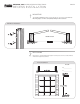
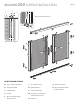
INSTALLING THE TOP AND BOTTOM GUIDE RAILS
Slide the B-Bottom Guide Rail fully onto the tabs on the A-Screen Cassette
End Cap [6.1].
NOTE: The Bottom and Top Rails each have decorative grooves on
one side. This groove should face the outside [6.2].
Slide the C-Top Guide Rail onto the tabs of the A-Screen Cassettes
Assembly [6.3].
A
C
6
6.1
6.3
6.2
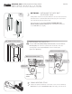
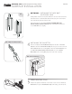
ADJUSTING THE HANDLES
Adjust the G-Handle heights by loosening the Allen-Head Set Screw, move the G-
Handle as desired and retighten screw.
8
K
K
G
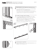
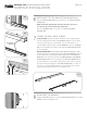
SECURE THE RAILS WITH SCREWS
C-Top Guide Rail Using the Decorative Trim Groove [6.2] as a guide, staying
above the glide platforms inside the Top Guide Rail, drill three (3) 1/8” (3mm)
holes at a location with one (1) positioned 4” in from each end and one (1)
centered. Drill through both sides of the Top Guide Rail. Secure the Top Guide
Rail to the entry with M-1/8” (3mm) x 1-3/4” (44 mm) Surface Mount Screws.
Do not overtighten.
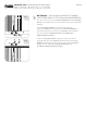
B-Bottom Guide Rail: Using the Decorative Trim Groove [6.2] as a guide
(staying underneath the glide platforms inside the Bottom Guide Rail), drill four
(4) 1/8”(3mm) holes as shown [7.1] and through both sides of the B-Bottom
Guide Rail. Secure the rails to the frame using M-1/8”(3mm) x 1-3/4”(44mm)
Surface Mount Screws. Do not over tighten. If the B-Bottom Guide Rail will
be positioned where it is susceptible to being stepped upon, kicked or otherwise
bent, then add structural support for the B-Bottom Guide Rail to rest upon. A
1/2” x 1/2” “L” shaped aluminum extrusion is recommended. This or another
support material may be purchased at a local hardware store.
7
B
M
M
M
M
M
M
C
7.1
DECORATIVE
GROOVES
C
B
B
A