
User Manual


3
English
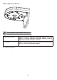
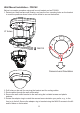
Accessories
II
Adaptor ring for FD8162
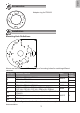
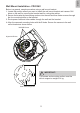
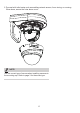
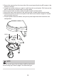
Installation
III
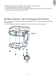
Above are the locations of different groups of mounting holes for matching different
cameras:
Hole Type Applicable Cameras Screw No. of
screws
A
FD8161 / FD7132 / FD7131
M4X15
2
FD8162 / FD8135H
4
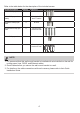
B
FD8133V / FD8134V
M4X8XD6 3
C
FD8133 / FD8134 / FD8131
M3X6 2
D
PZ7111 / PZ7112 / PZ7121 / PZ7122 / PZ7131 /
PZ7132 / PZ7151 / PZ7152 / PZ81x1W / PZ81x1
M3X4 2
E1
FD8335H / FD8361 / FD8361L / FD8362 / FD8362E /
FD8372
M4X15 4
E2
FD8361
(cables routed to the side of the bracket)
E3
FD8361
(cables routed to the side of the bracket)
For cabling and conguration details with each network camera, please refer to their
documentation.
Mounting Hole Denitions