Dome FE8181 Fixed Network Camera Quick Installation Guide P/N:625025700G Rev.: 1.0 All specifications are subject to change without notice. Copyright c 2014 VIVOTEK INC. All rights reserved.
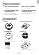
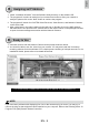
English Warning Before Installation Refer to your user's manual for the operating temperature. Do not place the Network Camera on unsteady surfaces. Do not touch the Network Camera during a lightning storm. Do not insert sharp or tiny objects into the Network Camera. Do not drop the Network Camera. Package Contents FE8181 Screws / Anchors / Cable tie Alignment Sticker Software CD D r i ll h o l e D ri ll h o l e 1 Power off the Network Camera as soon as smoke or unusual odors are detected.
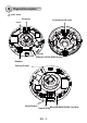
2 Physical Description Inner View Contacts Contacts for IR units Lens J7 J6 Ethernet 10/100 RJ45 Socket Headers Cabling Cutout Reset Button Status LEDs EN - 2 MicroSD/SDHC/SDXC Card Slot
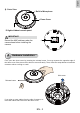
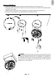
English Outer View Built-in Microphone Dome Cover IR lights hidden beneath panel IMPORTANT: 8181 083236 Record the MAC address under the camera base before installing the camera. 3 Hardware Installation First, open the dome cover by pressing the release button. You may squeeze the opposite edge of the dome cover if the dome cover does not come off easily. Then, follow the steps below to install the camera to either a ceiling or a wall.
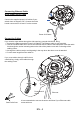
Connecting Ethernet Cable & the Power and IO Cable J7 Connect the supplied power & IO cables if your switch does not support PoE. Connect the white header connectors to J6 and J7 on the camera. J6 Power & IO Cable Connecting Cables If you need to route cables through the side opening, proceed with the following: 1. Connect the Ethernet and the Power & IO cables. The Ethernet cable is user-supplied. 2. Use the included cable ties to secure the Ethernet and IO cable to the base plate.
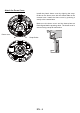
English Ceiling or Wall Mount 1. Attach the supplied alignment sticker for the camera base to the a ceiling or wall. 2. Using the circles on the sticker, drill pilot holes into the ceiling. Then hammer the supplied plastic anchors into the holes. 3. (Optional) Drill a cable hole on the ceiling/wall, and feed the cables through the hole. 4. Secure the camera base to the ceiling/wall with the supplied screws.
Attach the Dome Cover Install the plastic dome cover by aligning the snapfit tabs on the dome cover with the slotted tabs on the camera base. Install the dome cover by pressing it evenly to the camera base. Make sure the dome cover and the base plate are flush-aligned before pressing down. The dome cover is secured using a snap-fit mechanism.
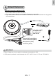
English 4 Network Deployment General Connection (without PoE) 1. Connect RJ45 Ethernet cable to a switch. 2. Connect the power cable from the Network Camera to a power outlet. 3. If you have external devices such as sensors and alarms, make the connection from the general I/O terminal block. POWER COLLISION 1 2 3 4 5 LINK RECEIVE PARTITION 1 3 +3V3 DO D1 GND +3V3: Power, 3.
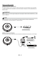
Power over Ethernet (PoE) When using a PoE-enabled switch The Network Camera is PoE-compliant, allowing transmission of power and data via a single Ethernet cable. Follow the below illustration to connect the Network Camera to a PoE-enabled switch via Ethernet cable. IMPORTANT: When IR lights are on in the night, the total power consumption is 23W. A 802.3at PoE PSE, e.g., PoE switch, is required. NOTE: 1. This equipment is only to be connected to PoE networks without routing to outside plants. 2.
English 5 Assigning an IP Address 1. Install “Installation Wizard 2” from the Software Utility directory on the software CD. 2. The program will conduct an analysis of your network environment. After your network is analyzed, please click on the “Next” button to continue the program. 3. The program will search for VIVOTEK Video Receivers, Video Servers, and Network Cameras on the same LAN. 4. After a brief search, the main installer window will pop up.
AR - 168
Dome FE8181 Fixed Network Camera Quick Installation Guide P/N:625025700G Rev.: 1.0 All specifications are subject to change without notice. Copyright c 2014 VIVOTEK INC. All rights reserved.