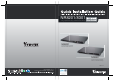
NR8201/8301 H.264 Compatible with VAST CMS Lockable HDD & Rack Mount Design NR8201 4-CH Viewing & Recording External eSATA Interface NR8301 8-CH Viewing & Recording RAID 0, 1 Scalable Storage Rev. 1.1 P/N: 625013601G Ver.1.1 Copyright c 2011 VIVOTEK INC. All rights reserved.
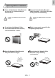
English Warning Before Installation Power off the Network Video Recorder as soon as it is found smoking or smelt unusual. Contact your distributor when such cases happen. Power PoE Status HDD WA N LAN1 LAN2 LAN3 LAN4 LAN5 LAN6 LAN7 Contact your distributor when such cases happen. Refer to your user's manual for the operating temperature. Do not place the Network Video Recorder around the heat sources, such as television or oven.
Do not touch the Network Video Recorder when it's lightening. Do not place the Network Video Recorder on unsteady surfaces. Power NR8301 Network Video PoE Recorder WAN Status LAN1 LAN2 LAN3 LAN4 LAN5 LAN6 LAN7 LAN8 HDD NR8301 Network Video Recorder Power Status Do not drop the Network Video Recorder.
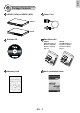
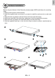
English 1 Package Contents NR8201 (4CH) or NR8301 (8CH) Power Cord NR8201 Power Status PoE WAN HDD LAN1 LAN2 LAN3 LAN4 NR8201 Network Video Recorder NR8301 NR8301 Network Video Recorder Power Status PoE WAN HDD LAN1 LAN2 LAN3 LAN4 LAN5 LAN6 LAN7 LAN8 Rack Mount Kit Software CD NR8201: Rack Mount Ear x 2 Screws x 4 (Black) Screws x 4 (Grey) Key x 2 NR8301: Rack Mount Ear x 2 Screws x 4 (Black) Screws x 8 (Grey) Key x 2 510000210G Quick Installation Guide Warranty Card E
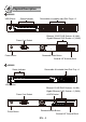
2 Physical Description NR8301 Removable & Lockable Hard Disk Trays x 2 Status Indicator USB Socket Power PoE Status HDD NR8301 Network Video Recorder WAN LAN 1 LAN 2 LAN 3 LAN 4 LAN5 LAN6 LAN7 LAN8 Ethernet 10/100 RJ45 Socket x 8 (LAN); Gigabit Ethernet RJ45 Socket x 1 (WAN) Power Cord Socket POWER AC IN 100V-240V Power Button RESET LAN2 LAN4 LAN6 LAN8 LAN1 LAN3 LAN5 LAN7 WAN 1 2 3 4 5 6 7 8 9 10 1112 Recessed Reset Button General I/O Terminal Block NR8201 Status Indicato
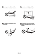
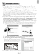
English 3 Hardware Installation Before using the Network Video Recorder, please prepare SATA hard disk(s) for recording video. 1. Make sure the power is disconnected. 2. Install the supplied rack mount ears if you want to install the enclosure into a rack cabinet. 3. Open the drive tray bezel as shown below and remove the drive trays. 4. Install your hard disk to the drive tray, and secure it with the supplied four screws. 5. Open the drive tray bezel and insert hard disk(s) into the drive bays. 6.
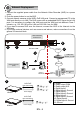
4 Network Deployment 1. Connect the supplied power cable from the Network Video Recorder (NVR) to a power outlet. 2. Push the power button to run the NVR. 3. Connect network cameras to the NVR’s PoE LAN ports. Connect a management PC to the WAN port directly or via LAN. The NVR comes with an embedded DHCP server for its LAN ports. It is necessary to configure the LAN ports and the WAN port into different Class C subnets, e.g., 192.168.100.xxx for LAN and 192.168.4.xxx for WAN. 4.
English 5 Assigning an IP Address 1. 1-1. If your local network does not have a DHCP server, you may temporarily connect a PC to a LAN port for initial configuration. The NVR comes with a default IP, 192.168.100.1. You can access the NVR server using this IP, and then manaully assign an IP to the NVR WAN port. 1-2. If your local network has a DHCP server, connect the WAN port to your local network, and use the IW2 utility to find the NVR server IP.
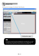
6 Ready to Use Following is the Homepage of the Network Video Recorder. Configuration page Note If you want to record live video and playback the recorded video, you have to add devices to the Network Video Recorder on the Configuration page. For further setup, please refer to user's manual on the software CD.
NR8201/8301 H.264 Compatible with VAST CMS Lockable HDD & Rack Mount Design NR8201 4-CH Viewing & Recording External eSATA Interface NR8301 8-CH Viewing & Recording RAID 0, 1 Scalable Storage Rev. 1.1 P/N: 625013601G Ver.1.1 Copyright c 2011 VIVOTEK INC. All rights reserved.