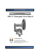
INSTALLATION MANUAL FLAT LCD DISPLAY MOUNT MODEL WB-31 Swingout Arm Mount
WB-31 TABLE OF CONTENTS Parts List Installation Tools Backplate Installation - Wood stud Backplate Installation - Concrete Surface WM-31 Installation Installing the Monitor Adjusting the Swingout Arm Adapter Plate Installation Technical Specifications Page 2 4 4 5 6 7 8 9 10 11 Installation Instructions
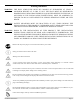
WB-31 Warning Statements WARNING: THE WALL STRUCTURE MUST BE CAPABLE OF SUPPORTING AT LEAST A MAXIMUM WEIGHT OF 50 LBS. IF NOT, THE WALL MUST BE REINFORCED. PROPER INSTALLATION PROCEDURE BY A QUALIFIED SERVICE TECHNICIAN, AS OUTLINED IN THE INSTALLATION INSTRUCTIONS, MUST BE ADHERED TO. FAILURE TO DO SO COULD RESULT IN SERIOUS PERSONAL INJURY, OR EVEN DEATH. WARNING: SAFETY MEASURES MUST BE PRACTICED AT ALL TIMES DURING THE INSTALLATION OF THIS PRODUCT.
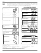
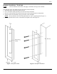
WB-31 Parts List NOTE: This mount is shipped with all intallation hardware and components. Make sure that none of these parts are missing and/ or damaged before beginning installation. If there are parts missing and/or damaged, please stop and contact TOA Electronics, Inc. 200x200 ADAPTER HARDWARE Swingout Arm (Qty 1) 1/4” Wedge Anchors (Qty 4). These are used only for concrete installations.
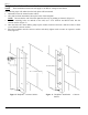
WB-31 Backplate Installation - Wood Stud NOTE: These installation instructions will apply to the WB-31 Swingout Arm Mount. The following steps will outline how the back plate will be mounted. 1. Determine where the mount location will be. 2. Use a stud finder (sold separately) to locate the nearest wall stud. 3. Once the wall stud has been located, dead-center of the wall stud must be determined. 4. After this has been determined, line-up the holes of the backplate.
WB-31 Backplate Installation - Concrete Surface NOTE: These installation instructions will apply to the WB-31 Swingout Arm Mount. The following steps will outline how the back plate will be mounted. 1. Determine where the mount location will be. 2. After this has been determined, line-up the holes of the backplate. NOTE: Be sure that the end of the back plate that has a lip is pointing as shown in (Figure 3). 3.
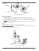
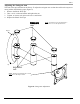
WB-31 WB-31 Installation 1. The reverse side of the mount must be mounted to the back plate that is attached to the wall. The back of the mount contains an elongated rectangle (Figure 5). Referring to Figure 5, the back plate receptacle must be placed over the top of the back plate, so that the entire mount “hangs” on the back plate. 2. Locate the access hole at the bottom of the mount base. Install the M6 x 35mm set screw with the M3 Allen wrench. 3.
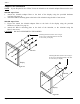
WB-31 (2) M4 x 10mm Phillips screws Display (2) M4 x 10 Phillips screws Figure 6. Monitor Installation Installing the Monitor 1. 2. Loosely tighten two (2) M4 x 10mm Phillips Head screws to the top of the mounting points. Insert the head of the screws through the keyhole slots and then secure the bottom two (2) M4 x 10mm Phillips Head screws to secure the flat panel to the mounts, then tighten the upper M4 x 10mm Phillips Head screws (Figure 6).
WB-31 Adjusting the Swingout Arm This unit comes pre-tensioned at the factory. To adjust the swingout Arm so that there will not be any movement, perform the following steps (Figure 8). 1. Remove the Plastic End Caps. 2. Take a 9/16” socket and ratchet and tighten the nut. 3. Tighten, or loosen, each joint to the user’s satisfaction. 4. Replace the Plastic End Caps. caps NOTE: The mount shown in this illustration is upside down to access the adjustment nuts.
WB-31 Adapter Plate Installation NOTE: If your flat panel is not a VESA 75/100, the 200x200 or the 100x200 Adapter Plates must be used. 100x200 Aapter Plate 1. Attach the 100x200 Adapter Plate to the back of the display using the provided hardware (see Parts List, page 4). 2. Attach the WB-31 mounting plate to the back of the 100x200 using the M4 x 5 mm screws. 200x200 Aapter Plate 3.
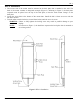
WB-31 Technical Specifications Figure 11.
WB-31 IN-WB31.R2 Page 12 E255449 29GZ WALL MOUNT Mfg.