VC-655 BT Digital Multimeter User Manual i
Table of Contents 1.Safety Information.............................................................................................................1 Safety Terms and Symbols.............................................................................................................1 General Safety Requirements........................................................................................................2 Measurement Limits.............................................................................
4.Measurement Tutorial.....................................................................................................31 Loading Errors (DC Voltage).........................................................................................................31 True RMS AC Measurements.......................................................................................................32 5.Troubleshooting.......................................................................................................
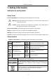
1.Safety Information 1. Safety Information Safety Terms and Symbols Safety Terms Terms in this Manual. The following terms may appear in this manual: Warning: Warning indicates the conditions or practices that could result in injury or loss of life. Caution: Caution indicates the conditions or practices that could result in damage to this product or other property. Terms on the Product. The following terms may appear on this product: Danger: It indicates an injury or hazard may immediately happen.
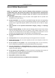
1.Safety Information General Safety Requirements Before any operations, please read the following safety precautions to avoid any possible bodily injury and prevent this product or any other products connected from damage. In order to avoid any contingent danger, this product is only used within the range specified. Use Proper Power Cord. Use only the power cord supplied with the product and certified to use in your country. Product Grounded.
1.Safety Information Measurement Limits The protection circuitry of the multimeter can prevent damage to the instrument and protect against the danger of electric shock, when the Measurement Limits are not exceeded.
1.Safety Information Measurement CAT II applies to protect against transients from energy-consuming equipment supplied from the fixed installation, such as TVs, PCs, portable tools, and other household circuits. Measurement CAT III applies to protect against transients in equipment in fixed equipment installations, such as distribution panels, feeders and short branch circuits, and lighting systems in large buildings.
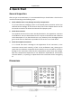
2.Quick Start 2. Quick Start General Inspection After you get a new multimeter, it is recommended that you should make a check on the instrument according to the following steps: 1. Check whether there is any damage caused by transportation. If it is found that the packaging carton or the foamed plastic protection cushion has suffered serious damage, do not throw it away first till the complete device and its accessories succeed in the electrical and mechanical property tests. 2.
2.
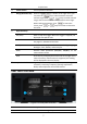
2.Quick Start 4 Power button 5 Range/Direction Keys When the Range softkey is shown on the right menu, you can press the key to switch between auto and manual range. Press or keys to enable manual range, and increase or decrease the measurement range. When setting a parameter, press to move the cursor, press or keys to increase or decrease the value. 6 Operation Keys 7 Turn on/off the multimeter. Run/Stop Start or stop auto trigger. When the trigger is stopped, the displayed data will be held.
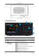
2.Quick Start 2 Line Fuse The fuse rating is 250 V, F1AL. To replace the fuse, see page 37, Appendix C: Line Fuse Replacement. 3 AC Mains Input AC mains input connector. User Interface Trigger Mode Display Trigger Status Icon Description Icon Auto trigger Description Auto record function is running Manual record Figure 2- 3 User interface (Single display) Figure 2- 4 User interface (Dual display) Power On (1) Connect the instrument to the AC supply using the supplied power cord.
2.Quick Start Warning: To avoid electric shock, the instrument must be grounded properly. (2) Press down the power button at the front panel, the screen shows the boot screen.
2.Quick Start Measurement Connections After selecting the desired measurement function, please connect the signal (device) under test to the multimeter according to the method below. To avoid instrument damage, do not discretionarily switch the measurement function when measuring.
2.
3.Functions and Operations 3. Functions and Operations To Set the Range The instrument provides auto and manual range. In auto range, the multimeter selects a proper range automatically according to the input signal; in manual range, you can use the front panel key or menu softkey to set the range. The auto range can bring a lot of convenience for users while the manual range provides higher reading precision. 1st Method: Use the front panel key to set the range.
3.Functions and Operations Measurement Speed The instrument provides three types of measurement speed: "Low" speed is 4 reading/s; "Mid" speed is 16 reading/s; "High" speed is 65 reading/s. In DCV, ACV, DCI, ACI and resistance measurements, the measurement speed is selectable. Basic Measurement Functions Measuring DC Voltage This section describes how to configure DC voltage measurements. Operating Steps: 1. Enable the DCV measurement. Press on the front panel to enter DCV measurement mode. 2.
3.Functions and Operations 5. Set the measurement speed. Press the Speed softkey to switch between Low, Mid and High. See page 14 ” Measurement Speed”. 6. Set the relative value. Press the Rel softkey to turn on or off the relative operation. For relative operation, the multimeter subtracts the pre-specified value of REL operation from the actual measurement result and displays the result. See page 26, Relative Value. Measuring AC Voltage This section describes how to configure AC voltage measurements.
3.Functions and Operations 6. Set the relative value. Press the Rel softkey to turn on or off the relative operation. For relative operation, the multimeter subtracts the pre-specified value of REL operation from the actual measurement result and displays the result. See page 26, Relative Value. Measuring DC Current This section describes how to configure DC current measurements. Operating Steps: 1. Enable the DCI measurement. Press on the front panel to enter DCI measurement mode. 2. Set the function.
3.Functions and Operations Press the Speed softkey to switch between Low, Mid and High. See page 13, “Measurement Speed “. 6. Set the relative value. Press the Rel softkey to turn on or off the relative operation. For relative operation, the multimeter subtracts the pre-specified value of REL operation from the actual measurement result and displays the result. See page 26, Relative Value. Measuring AC Current This section describes how to configure AC current measurements. Operating Steps: 1.
3.Functions and Operations 4. Set the range. Press the Range softkey to set the range. Auto range automatically selects the range for the measurement based on the input. Note: The multimeter uses two kinds of fuses for current protection: A 10A fuse is built into the 10A input terminal for overcurrent protection, and a 600mA fuse is built into the uAmA input terminal for overcurrent protection. 10% over range for all ranges except 10 A range. If the reading exceeds 10.
3.Functions and Operations 3. Set the range. Press the Range softkey to set the range. Auto range automatically selects the range for the measurement based on the input. Note: 1000 V input protection is available in all ranges. 10% over range for all ranges except 50 MΩ range. If the reading exceeds 55 MΩ in 50 MΩ range, "overload" will be displayed. 4. Set the measurement speed. Press the Speed softkey to switch between Low, Mid and High. See page 13, Measurement Speed . 5. Set the relative value.
3.Functions and Operations 2. Connect the test lead. 3. Set the beeper. Press the Beeper softkey to enable or disable the beeper. When the beeper is enabled, the reading is below 30 Ω, the multimeter will beep continuously. 4. Set the short-circuit resistance. Press the Threshold softkey to set the short-circuit resistance. Press the front panel key to move the cursor, press or keys to increase or decrease the value. The range for the 1 Ω to 1000 Ω. The default is 50 Ω. 5.
3.Functions and Operations 2. Connect the test lead. 3. Set the beeper. Press the Beeper softkey to enable or disable the beeper. When the beeper is enabled, the diode is connected, the multimeter will beep continuously. 4. Diode measurements behave as follows: Forward pressure drop of diode 0 to 3 V >3V Display and beep Displays measured voltage, and the multimeter beeps when the voltage is below 0.
3.Functions and Operations 2. Connect the test lead. Tip: Please short contact the two feet of an electrolytic capacitor by using a test lead before measuring the electrolytic capacitor. 3. Set the range. Press the Range softkey to set the range. Auto range automatically selects the range for the measurement based on the input. Note: 1000 V input protection is available in all ranges. 10% over range for all ranges except 50000 μF range.
3.Functions and Operations 2. Connect the test lead. 3. Note Frequency range: 20 Hz to 60 MHz. 750 V input protection is available in all ranges. 4. Set the relative value. Press the Rel softkey to turn on or off the relative operation. For relative operation, the multimeter subtracts the pre-specified value of REL operation from the actual measurement result and displays the result. See page 26, Relative Value. Measuring Temperature This section describes how to configure temperature measurements.
3.Functions and Operations 3. Set the sensor configuration file. Press the Load softkey, choose KITS90 or Pt100. 4. Set the display. Press the Display softkey to set the display mode of the result. Temp: only the temperature value will be displayed; measure: only the measurement value will be displayed. All: both the temperature value (on the main display) and the measurement value will be displayed. 5. Set the temperature unit.
3.Functions and Operations Dual Display Using dual display function, you can view the readings of two measurement functions simultaneously. Figure 3- 1 Dual Display Operating Steps: 1. Press one of the measurement function keys to turn on the primary measurement function. 2. Press on the front panel, the secondary function list is shown on the right menu, select the desired function. 3. When dual display is enabled, press to switch the primary function and the secondary function.
3.Functions and Operations Data Hold Data hold keeps the current reading on the display. (1) Press the Run/Stop panel key to stop the trigger, and the current reading is kept on the display screen. (2) Press the Run/Stop key again to continue triggering. Math The multimeter provides these math functions: Max/Min, dB/dBm and relative. Only one operation can be enabled in the Max/Min, dB/dBm, or relative operation.
3.Functions and Operations dB Function dB represents the relative value which is used in the relative operation of dBm value. When enabled, the multimeter calculates the dBm value of the reading and subtracts the preset dB from this value and then displays the result: dB = 10 x Log10 ( reading2 / reference resistance / 1 mW) - dB preset Press the Rel R softkey to select the reference resistance.
3.Functions and Operations Data Record Function Data record function includes manual record and auto record. You can use any or both functions to record the data. Manual and automatic records share a table of data stored in internal storage. The maximum number of recorded points is 1000. After collecting the data, it can be exported to the computer. Manual record: Press the to the DB data.
3.Functions and Operations Press the Interval softkey to specify the time interval between readings. The range is 15 ms to 9999.999 s. 2. Record data: Press the Start softkey to start auto record. The icon will show up on the top of the display. Press the End softkey to stop recording, the data table shows the readings taken. Press or keys to turn the page. Note: Automatic recording function supports switching measurement function.
3.Functions and Operations Utility Menu You can set the parameters of the system-related functions and port parameters in utility menu. Press the panel key to view the instrument model, firmware version, serial number, and checksum. Language Press the front panel key, press the Language softkey to switch display languages. Backlight Press the front panel key, press the Backlight softkey to adjust the brightness. Clock Press the front panel key, press the RTC softkey.
3.Functions and Operations Type Utility Port Math Record Others Item Backlight Baud Parity Stop Bits Data Bits Max/Min dB/dBm Off/On Function Rel R dB Rel Auto Manual Point Interval Auto On/Off Run/Stop Rel Beeper Threshold Freq Mode Unit Dual Display Load Mode Range Speed Value 100% 115200 None 1 8 Off Off dB 50Ω 0Ω Clear Clear 100 1S Off Run Off Off 50Ω Freq ℃ Off All KITS90 DVC Auto Low Communication interface settings Press the front panel interface setting menu.
4.Measurement Tutorial 4. Measurement Tutorial Loading Errors (DC Voltage) Measurement loading errors occur when the resistance of the DUT(Device-Under-Test) is an appreciable percentage of the multimeter's input resistance, as shown below. Vs = ideal DUT voltage Rs = DUT source resistance Ri = multimeter input resistance Error (%) 100 Rs Rs Ri For the mV range, input impedance≥ 5 MΩ. For other range, input impedance≥10 MΩ.
4.Measurement Tutorial True RMS AC Measurements The AC measurement of the multimeter has true RMS response. Power dissipated in a resistor is proportional to the square of an applied voltage, independent of the wave shape of the signal. This multimeter accurately measures true rms voltage or current, as long as the wave shape contains negligible energy above the meter’s effective bandwidth. The effective AC voltage bandwidth of the multimeter is 1 kHz, while the effective AC current bandwidth is 1 kHz.
5.Troubleshooting 5. Troubleshooting 1. The instrument is powered on but no Display. 1) Check if the power is connected properly. 2) Check if the line fuse which is below the AC Mains Input is used appropriately and in good condition (see page 37, Appendix C: Line Fuse Replacement). 3) Restart the instrument after the steps above. 4) If the problem still exists, please contact us for our service. 2. The reading does not change when a current signal is input.
6.Technical Specifications 6. Technical Specifications Function DC Voltage True RMS AC Voltage[4] DC Current Range[2] Resolution Accuracy: ± (% of reading + LSB) 50.000 mV 0.001 mV 0.1% + 10 500.00 mV 5.0000 V 50.000 V 500.00 V 1000.0 V[3] 0.01 mV 0.0001 V 0.001 V 0.01 V 0.1 V 0.05% + 5 0.05% + 5 0.05% + 5 0.1% + 5 0.1% + 10 20 Hz – 45 Hz 1% + 30 45 Hz – 65 Hz 0.5% + 30 65 Hz – 1 kHz 0.7% + 30 500 uA 0.01 uA 0.15% + 20 5000 uA 0.1 uA 0.15% + 10 50 mA 0.001 mA 0.
6.Technical Specifications [5] 30 seconds OFF after 30 seconds ON is recommend for the continuous current that higher than DC 7 A or AC RMS 7 A. [6] Specifications are for amplitude of sine wave input > 0.5% of range. For inputs from 1% to 5% of range, add 0.1% of range extra error. [7] Specifications are for 2–wire ohms using the relative operation of math. Without relative operation, add ±0.20 Ω additional error in 2-wire ohms function.
7.Appendix 7. Appendix Appendix A: Enclosure Standard Accessories (subject to final delivery): Power Cord Test lead Crocodile clip Safety hintsheet CD Rom USB Cable Quick Guide Spare Fuse Appendix B: General Care and Cleaning General Care Do not store or leave the instrument where the liquid crystal display will be exposed to direct sunlight for long periods of time. Cleaning To clean the instrument exterior, perform the following steps: 1.
7.Appendix Appendix C: Line Fuse Replacement The line fuse is in the plastic fuse box below the power line input on the rear panel. Warning: Disconnect the line cord at the rear panel and remove all test leads connected to the instrument before replacing the line fuse. Failure to do so could expose the operator to hazardous voltages that could result in personal injury or death. Use only the correct fuse type. Failure to do so could result in personal injury or instrument damage.