VC-655 BT Digital Multimeter Quick Guide i
Table of Contents 1.Safety Information.............................................................................................................1 Safety Terms and Symbols.............................................................................................................1 General Safety Requirements........................................................................................................2 Measurement Limits.............................................................................
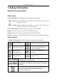
1.Safety Information 1. Safety Information Safety Terms and Symbols Safety Terms Terms in this Manual. The following terms may appear in this manual: Warning: Warning indicates the conditions or practices that could result in injury or loss of life. Caution: Caution indicates the conditions or practices that could result in damage to this product or other property. Terms on the Product. The following terms may appear on this product: Danger: It indicates an injury or hazard may immediately happen.
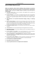
1.Safety Information General Safety Requirements Before any operations, please read the following safety precautions to avoid any possible bodily injury and prevent this product or any other products connected from damage. In order to avoid any contingent danger, this product is only used within the range specified. Use Proper Power Cord. Use only the power cord supplied with the product and certified to use in your country. Product Grounded.
1.Safety Information Measurement Limits The protection circuitry of the multimeter can prevent damage to the instrument and protect against the danger of electric shock, when the Measurement Limits are not exceeded.
1.Safety Information Measurement CAT II applies to protect against transients from energy-consuming equipment supplied from the fixed installation, such as TVs, PCs, portable tools, and other household circuits. Measurement CAT III applies to protect against transients in equipment in fixed equipment installations, such as distribution panels, feeders and short branch circuits, and lighting systems in large buildings.
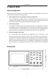
2.Quick Start 2. Quick Start General Inspection After you get a new multimeter, it is recommended that you should make a check on the instrument according to the following steps: 1. Check whether there is any damage caused by transportation. If it is found that the packaging carton or the foamed plastic protection cushion has suffered serious damage, do not throw it away first till the complete device and its accessories succeed in the electrical and mechanical property tests. 2.
2.Quick Start Foot Stool Adjustment Unfold the foot stool on the bottom of the multimeter.
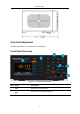
2.Quick Start 3 Measurement Function Keys DC or AC voltage measurements DC or AC current measurements Resistance, continuity, and diode measurements Capacitance measurements Frequency/Period measurements Temperature measurements 4 Power button 5 Range/Direction Keys When the Range softkey is shown on the right menu, you can press the key to switch between auto and manual range. Press or keys to enable manual range, and increase or decrease the measurement range.
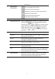
2.Quick Start Rear Panel Overview Figure 2- 2 Rear panel overview Item Name Description 1 USB Device Connect the PC through this port. 2 Line Fuse The fuse rating is 250 V, F1AL. To replace the fuse, see page 16, Appendix C: Line Fuse Replacement. 3 AC Mains Input AC mains input connector.
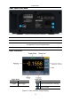
2.Quick Start Figure 2- 4 User interface (Dual display) Power On (1) Connect the instrument to the AC supply using the supplied power cord. Warning: To avoid electric shock, the instrument must be grounded properly. (2) Press down the power button at the front panel, the screen shows the boot screen.
2.Quick Start Measurement Connections After selecting the desired measurement function, please connect the signal (device) under test to the multimeter according to the method below. To avoid instrument damage, do not discretionarily switch the measurement function when measuring.
2.
2.Quick Start Data Record Function Data record function includes manual record and auto record. You can use any or both functions to record the data. Manual and automatic records share a table of data stored in internal storage. The maximum number of recorded points is 1000. After collecting the data, it can be exported to the computer. Manual record: Press the to the DB data.
2.Quick Start 1 to 1000. Press the Interval softkey to specify the time interval between readings. The range is 15 ms to 9999.999 s. 2. Record data: Press the Start softkey to start auto record. The icon will show up on the top of the display. Press the End softkey to stop recording, the data table shows the readings taken. Press or keys to turn the page. Note: Automatic recording function supports switching measurement function.
3.Troubleshooting 3. Troubleshooting 1. The instrument is powered on but no Display. 1) Check if the power is connected properly. 2) Check if the line fuse which is below the AC Mains Input is used appropriately and in good condition (see page 16, Appendix C: Line Fuse Replacement). 3) Restart the instrument after the steps above. 4) If the problem still exists, please contact us for our service. 2. The reading does not change when a current signal is input.
4.Appendix 4. Appendix Appendix A: Enclosure Standard Accessories (subject to final delivery): Power Cord Test lead Crocodile clip Safety hintsheet CD Rom USB Cable Quick Guide Spare Fuse Appendix B: General Care and Cleaning General Care Do not store or leave the instrument where the liquid crystal display will be exposed to direct sunlight for long periods of time. Cleaning To clean the instrument exterior, perform the following steps: 1.
4.Appendix Appendix C: Line Fuse Replacement The line fuse is in the plastic fuse box below the power line input on the rear panel. Warning: Disconnect the line cord at the rear panel and remove all test leads connected to the instrument before replacing the line fuse. Failure to do so could expose the operator to hazardous voltages that could result in personal injury or death. Use only the correct fuse type. Failure to do so could result in personal injury or instrument damage.