
Instructions

Safety instructions and hazard warnings
This device has left our factory premises in a safe and perfect condition.
We kindly request the user to observe the safety instructions and warnings contained in
the enclosed operating instructions so this condition is maintained and to ensure safe
operation.
• Damages due to failure following these operating instructions will void the warranty! We do not
assume any liability for any resulting damage!
• We do not assume any liability for personal injuries and material damages caused by the
improper use or non-compliance with the safety instructions! Any warranty will be void in
such cases.
• Theunauthorisedconversionand/ormodicationoftheunitisnotpermittedforsafetyand
approval reasons.
• For any work carried out, the accident prevention regulations of the Employer’s Liability Insur-
ance Association for Electrical Systems and Operating Facilities must be observed
• In schools, training facilities, hobby and self-help workshops the use of gauges and testers
shouldbesupervisedinaresponsiblemannerbyqualiedtrainedstaff.
• Extracareshouldbetakenwhenusingthedeviceforthersttime.Therefore,pleasefollow
the operating instructions carefully.
• Thevoltagevaluesspeciedonthevoltagetesterarenominalvoltages.
• The device may not be exposed to extreme temperatures, strong vibrations or high humidity.
The readout is only ensured within a temperature range of -15 to +55 °C and a relative air
humidity of max. 85% (non-condensing).
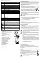
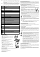
• Hold the voltage tester only by the designated gripping areas (1 and 16). Never reach beyond
the tactile barrier of the gripping areas (5 and 13).
• Always check that the voltage tester is working properly prior and after employment. Measure
aknownvoltagesource(e.g.mainsvoltage230V/AC)rst,andchecktheaccuracyofthe
readout. Don’t use the voltage tester any longer, in case one or more indication ranges fail
to function.
• The housing of the voltage tester may not be dissembled except for opening the battery com-
partment cover.
• The voltage tester may only be used on systems within the voltage ranges given.
• The next higher voltage range on the level indicator starts at 0.85 times the nominal value
already.
• The applicable DC voltage limit value for hazardous contact voltage (in accordance with DIN
VDE 0100, part 410) is indicated by the light indicator at 120 V.
• The applicable DC voltage limit value for hazardous contact voltage (in accordance with DIN
VDE 0100, part 410) is indicated by the light indicator at 50 V.
• The voltage tester only works correctly on grounded low voltage systems. Improper grounded
equipment or insulated body protectors can have an adverse effect on the readout.
• If the neutral wire (N) or the earth wire (PE) is interrupted, no readout will be displayed!
• Keep the voltage tester in a clean condition, and store it properly in a dry place.
• This device is not a toy and should be kept out of the reach of children.
• To prevent injuries place the probe tip protection back on the test probes, if the tester is not
used.
• When using the voltage tester in the range of the measurement categories CAT III and CAT
IV, it is recommended to push the included plastic protective sheath (2) over the test probes
in order to reduce the exposed length of contact tips. This will reduce the risk of a possible
short circuit during metering.
• Depending on the internal impedance of the voltage tester, there are different ways of display-
ing “operating voltage present” or “operating voltage not present” in the presence of interfer-
ence voltage.
• A voltage tester with relatively low internal impedance does not display all interference volt-
ageswithaninitialvalueaboveELV,comparedtothereferencevalueof100kΩ.Uponcontact
with the parts to be tested, the voltage tester may temporarily reduce the interference voltage
by discharging to a level below ELV; however, after removing the voltage detector, the interfer-
ence voltage will assume its original value again.
• Whenthenotication“voltagepresent”doesnotappear,itisstronglyrecommendedthatyou
insert the earthing device before starting work.
• A voltage tester with relatively high internal impedance will not clearly display “operating volt-
age present” in the event of existing interference voltage, compared to the reference value
of100kΩ.
• When “voltage present” appears on a part which is considered disconnected from the system,
it is strongly recommended to check the state “operating voltage not present” with additional
measures (e.g., using a suitable voltage tester, visual inspection of the disconnection point
in the electrical network, etc.) to make sure the voltage indicated by the voltage tester is not
a fault.
• A voltage tester indicating two values of the internal impedance has passed the design test for
handling interference voltages and is able to differentiate (within technical limits) the operating
voltage from the interference voltage and directly or indirectly display the existing voltage type.
CAT I Measurement Category I is applicable to measuring circuits of electrical and electronic equip-
ment that is not directly supplied with mains voltage (battery-operated devices, etc.)
CAT II Measurement Category II is applicable to measuring circuits of electrical and electronic equip-
ment that is directly supplied with the mains voltage via a power plug. This category also
covers all smaller categories (e.g. CAT I for measuring signal and control voltages).
CAT III Measurement Category III is applicable to measuring circuits of installations in buildings (e.g.
electric sockets or sub-distributions). This category also covers all smaller categories (e.g.
CAT II for measuring electronic devices).
Measurement Category IV is applicable to measuring at the origin of the low-voltage installa-
tion (e.g. main distribution, electricity provider’s transfer points to homes, etc.) and outdoors.
This category also contains all lower categories.
Operating instructions
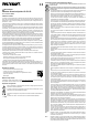
Two-Pole Voltage Tester VC-55 LCD
Item no. 1188073
Intended use
The two-pole voltage tester is a portable test device that detects and indicates the voltage levels of low volt-
age circuits. It is intended to indicate DC and AC voltages in the range of 12 to 690 V, and polarity by applying
bipolar. The voltage ranges are represented in 7 levels.
Starting at a nominal voltage of 38V/ACor38V/DC,awarningindicatorforthevoltagerangeswillash
signalizing the warning of dangerous voltage. This warning indication is also displayed when the batteries
are empty.
The voltage tester complies with the standard for two-pole voltage testers (EN 61243-3/DIN VDE 0682-401)
and protection type IP64 (dust and splash proof), and is intended for dry or damp indoor and outdoor loca-
tions. Operating the device during rainfall or precipitation is not permitted. The voltage tester is designed for
usebyqualiedelectriciansinconjunctionwithpersonalprotectiveequipment.
The device features an LCD display with an indicator of the test voltage real value, an audio-visual continuity
tester, built-in measurement point light and the function “single pole” phase tester. For the tester to function
two micro batteries (type AAA/LR03) are required. Operation with rechargeable batteries is not permitted.
A phase sequence indicator for grounded three-phase current is available.
The voltage tester shall only be utilized in systems of the electrical measurement category CAT III (domestic
installations / sub-distributions) up to 1000 V or in CAT IV (at the origin of the low-voltage installations) up
to 600 V to ground potential.
These measurement categories also comprise all of the smaller measurement categories (e.g. CAT II and
CAT I).
The voltage tester must be clasped by the two handles (1 and 16) while taking measurements. Do not touch
beyond the tactile barriers of the gripping area (5 and 13). Do not cover the indicator panel and do not touch
metal contacts and measurement points.
Follow also any additional safety instructions contained in this manual.
Do not use under adverse ambient conditions. Unfavourable ambient conditions are:
- Excessive humidity or dampness
- Dustandammablegases,vapoursorsolvents
- Potentially explosive atmosphere (Ex)
- Thunderstormsorsimilarweatherconditionssuchasstrongelectrostaticelds,etc.
Use other than that described above can lead to damage to the product and may involve additional risks
suchas,forexample,shortcircuits,re,electricalshocksetc.Nopartoftheproductmaybemodiedor
converted! The safety instructions are to be observed without fail!
Package contents
• VC-55 with captive probe tip protection
• 2 terminal screws (Ø 4 mm, applicable for CAT II)
• 2 plastic protective sheaths, applicable for CAT III/CAT IV
• 2 micro batteries (AAA/LR03)
• Operating instructions
Up-to-date operating instructions
Download the latest operating instructions via the link www.conrad.com/downloads or scan the QR code.
Follow the instructions on the websit
Symbol explanation
An exclamation mark in a triangle indicates important information contained in these operating
instructions that must be observed by all means.
The lightning symbol in a triangle warns of electric shock danger or the impairment of the electri-
cal safety of the appliance.
This device is CE compliant and therefore meets the necessary national and European guide-
lines.
The arrow symbol is used where special tips and notes on operation are provided.