
Instructions
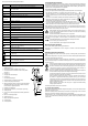

Please pay attention to the following symbols and labels:
L1 - Probe for phase L1, negative potential at DC
L2 + Probe for phase L2, single pole phase test, positive potential at DC
V AC DC V AC = alternating current
V DC = direct current
Display + Positive potential at probe L2 +
Display - Negative potential at probe L2 +
Display + - AC voltage (both indicators for + and - are on)
12/24/50/120
230/400/690
Display of rated voltage range in volt (V)
Rx Display for continuity test
kΩ Electrical resistance in kilo-ohm
f Rated frequency range of electr. voltage
I TestcurrentisspeciedinmA(milliampere)
W Electrical test load in watts
Hz Electrical frequency (Hertz)
Temp °C Permitted operating temperature range in ° Celsius
ON Maximum duty cycle (DC) in seconds (s)
OFF Minimum operating pause after a test cycle in seconds (s)
Date Year of manufacture
OL Overowindication.Measuringrangeexceeded
- - - - Power indicator on the display
Warning of hazardous voltage (>38 V/AC, >38 V/DC (also functions when batteries
are empty or even without batteries).
Symbol for buzzer alarm
Apparatus and equipment for live works. Personal protective measures are
essential.
Rotarydirectioneldindicatorongroundedthree-phasenetworks.L=leftturning,
R = right turning
Protection class 2 (double or reinforced insulation/ protective insulation)
Symbol for the battery data used.
2x 1.5 V micro batteries, LR03, AAA
Replace battery indicator on display. The batteries must be replaced immediately, if
this symbol appears.
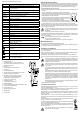
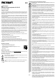
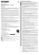
Description of component parts
1 Handle probe tip L1 (-)
2 plastic protective sheaths, applicable for CAT III/CAT IV
3 4 mm terminal screws to test outlets from the front side (built-in
outlet! CAT II)
4 Probe tip L1 (-)
5 Hand grip barrier with fastening bar
6 Probe tip L2 (+)
7 LED measurement point light
8 LED level indicator for voltage ranges and polarity
9 Covered sound opening for alarm buzzer
10 Warning of hazardous voltage (>38 V/AC, >38 V/DC (also indicated
when batteries are empty or even when no batteries are present).
Phase indicator for single-pole phase test
11 Rx indicator for continuity test
12 Rotarydirectioneldindicator(L=leftturning/R=rightturning)
13 Handle grip barrier
14 LCD screen for nominal voltage indicator and battery replacement
indicator
15 Button for LED metering point light
16 Handle probe tip L2 (+)
17 Battery compartment with bayonet lock
18 Connecting cable
19 Probe tip protection
Inserting/replacing the batteries
The voltage tester needs battery power for its basic function as a two-pole voltage tester with a voltage range
indicator and its additional functions such as metering point light, continuity test, phase sequence indication
or “single pole” phase tester. Two micro batteries (type AAA/LR03, included in delivery) are required for this
purpose. The use of rechargeable batteries is not permitted.
To insert/replace the battery, proceed as follows:
• Remove the voltage tester from all metering points and attach the protective cover to the probes.
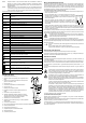
• Openthebatterycompartment(17)byreleasingthelockwithaatobject(e.g.
wide slot screwdriver) in a 90° counter-clockwise rotation. At its side, a small
groove is exposed that allows you remove the battery compartment cover from
the device.
• Insert two new micro-batteries (LR03/AAA) into the battery compartment. Pay at-
tention to the polarity indicated on the battery compartment cover. If possible, use
alkaline batteries. They guarantee a longer service life.
• Close and lock the battery compartment in reverse order. Make sure that the seal-
ing ring on the battery compartment does not get pinched or damaged. There is only one position for the
battery compartment cover to match the device. The groove must be located on the right.
Battery replacement is necessary when the level indicator (8) is no longer illuminated during the function test,
or the battery replacement symbol appears on the LCD, or if you cannot hear the signal sound any longer,
when the contacts of the two probes (4 and 6) are in contact.
When the batteries are empty, only the warning indicator (10) for “Dangerous Voltage” will func-
tion when the test voltage reaches 38 V/AC or 38 V/DC. Do not ever touch the measuring
contacts, if this indicator is on.
Operation while the battery compartment is open, is not permitted.
To prevent damage to the device from leaking batteries, remove the batteries from the device if you will
notbeusing itforalongerperiod.Forthe samereason,werecommendthatyouremove atbatteries
immediately.
Compatible alkaline batteries can be obtained with the following order number:
Item no. 652303 (2 pcs. Please order 1x unit).
Only use alkaline batteries; they are high-performance and durable.
Mesurement points illumination
The VC-55 has a battery-operated measuring point illumination.
Press button (15) to turn illumination on and off. The light is on for about 130 seconds and disappears
automatically.
Performing tests and measurements
The two-pole voltage tester consists of the two probes (4 and 6), a connecting cable (18) and the indicator
panel.
Always hold the voltage tester in a way, that you can look down onto the indicator panel. Illuminated indica-
tors may be adversely affected by strong light.
For DC measurements, the probe tip L2+ (6) is the positive pole, and the probe tip L1- (4) is the negative pole.
The VC-55 will autonomously turn on when the test starts (entry level >10 V), and when the test has been
completed, it turns off.
Always check that the voltage tester is functioning properly prior and after employment. Measure
aknownvoltagesource(mainsvoltage230V/AC,forexample)rst,andchecktheaccuracyof
the readouts. In the event of one or more indicating ranges (8) fail, do not use the voltage tester.
If the meter does not display any function or individual indicator ranges are not functioning, de-
commission the voltage tester. A defective voltage tester must not be used.
Observe the regulations regarding work with electrical systems. Personal protective equipment
must be used when working on systems with dangerous electrical voltage.
The maximum permitted duty cycle (ON) is 30 seconds. After that time has passed, an opera-
tional rest of 240 minutes at least, has to be maintained.
When the indication “voltage present” appears on a part that is expected to be disconnected of
theinstallation,itishighlyrecommendedconrmingbyanothermeans(e.g.useofanadequate
voltage detector, visual check of the disconnecting point of the electric circuit, etc.) that there is no
operating voltage on the part to be tested and to conclude that the voltage indicated by the voltage
detector is an interference voltage.
When the indication “voltage present” does not appear, it is highly recommended installing
earthing equipment before work.
The following measurement functions can be conducted:
a) Two-pole voltage metering
Always hold the voltage tester by the handles designed for this purpose (1 and 16). Never reach beyond the
tactile barrier of the grip (5 and 13).
Guide the two probe tips onto the measurement points to be tested. The voltage range is shown on the level
indicator (8) and the present measuring voltage is shown on the LCD display.
The light indicators (+) and (-) show the type of voltage and the corresponding polarity. If both indicators, LED
(+) and (-) are lit at the same time, alternating current (AC) is present. Polarity is only indicated by means
of the two LEDs.