
Technical data

29
Assembly
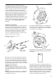
housing apart using a screwdriver in the groove
provided, at the same time as you hold the leaf spring
(19) out to allow the full load limiter to loosen from the
volume screw (9). The outer part of the smoke limiter
housing, including the spring, piston and volume
screw, can now be removed. Unscrew the holder (17)
(internal 8 mm socket) and press it out of the smoke
limiter housing, after which the diaphragm (12) can be
undone and can be changed. It is good practice to
change the O-ring (18) at the same time. On re-
assembly, coat the contact face of the volume screw
(9) against the O-ring (18) and the holder (17), and the
surface of the holder against the diaphragm with
silicone grease, such as MOLYKOTE® PG 54
Plastislip.
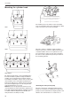
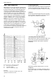
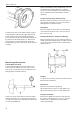
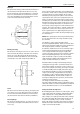
Adjustment, smoke limiter
Screw in the maximum volume screw (9) to make the
dimension (B) from adjustment nut (15) 7 mm and
dimension (A) between adjustment nut (15) and stop
nut (16) 0.3 mm. These dimensions are default values,
which correspond to the median values of adjust-
ments made in production. If dimension (A) is in-
creased, i.e. adjustment nut (15) is screwed out, the
amount of visible smoke is reduced.
MOLYKOTE
®
is a trade mark owned by the
Dow Corning Corporation
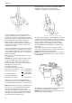
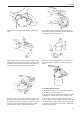
9. Install the oil pump’s gearwheel according to the
marks (from the disassembly). Insert a new O-ring in
the timing gear cover. Oil the gear wheel and fit the
cover using a new sealing ring.
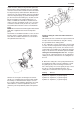
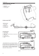
8A. Insert the control rod through the block and into
the transmission housing. Install the bearing ball (1)
onto the control rod and insert the control rod through
the hole in the control arm (2). Install the spring (3)
which guides the control rod. Models 2001 and 2003T
have two springs and a washer, see fig. Screw on the
end nipple (4) until it bottoms.
NOTE! Do not use any tools.
Screw in the upper bolts (with their copper sealing
washers) that guide the control rod. Then, screw the
lower bolts that hold the control rod in place in the en-
gine block.
NOTE! The lower bolts should not have sealing wash-
ers. Apply Permatex to the threads. Check that the
control rod moves freely.
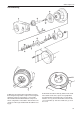
10. Insert the key for the pulley in the crankshaft and
install the pulley. Tightening torque 40 Nm (4,0 kpm)
(29.5 ft.lbs).
11. Clean the valve lifters carefully and coat the con-
tact surface against the camshaft with molybdenum
disulphide. Oil the valve guides in the block and install
the lifters. Clean the roller lifters of the fuel injection
pumps and install then in the block. Lock the roller lift-
ers with screws through the block after the installation
(apply Permatex to the threads). Check carefully to
make sure that the lifters are correctly installed and
that they are running easily in the groove.