
Technical data

32
Assembly
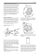
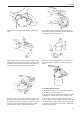
C. Turn cylinder no. 1 to it’s injection position.
Place the guide pin (2b) in the setting-disc’s hole
marked cyl. 1. Turn the crankshaft a little against
the normal direction of rotation and thereafter in the
normal rotation direction until the setting-disc’s
guide pin (2b) goes in the timing cover’s hole.
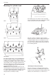
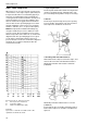
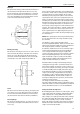
Measure using a caliper the distance between the
cylinder block and the roller lifter’s edge (do not
measure on the roller).
Based on the dimension measured, shims shall be
selected so that: Measured dimension + shim = ref-
erence dimension. When the reference dimension
has been achieved, this gives the correct injection
angle for the engine.
Please refer to Technical Data, page 12, for refer-
ence dimensions.
Example: The injection angle for a 2003-D is to be
set after camshaft replacement. Using tool no.
884787 set to 22°, the measured dimension is
55.0 mm (2.16535"). The reference dimension for
2003-D is 55.4 mm (2.18110").
The pump is marked 2.
The shim thickness then becomes:
The reference mesurement 55.4 (2.181102 in.)
The measured distance – 55.0 (2.165354 in.)
= 0.4 (0.015748 in.)
The pump marking 2 – 0.2 (0.007874 in.)
(= 0.2 mm /.007874 in.)
Shim thickness required 0.2 (0.007874 in.)
In this case, use one soft 0.2 mm (0.007874")
shim. Mark the block “4” and install the pump with
the selected shim(s). Cylinder no. 1 is now set to 16°.
NOTE! A hard shim must always be fitted between
two soft ones, never together with another hard
shim or directly against the block or pump.
Hard shims are available in thicknesses 0.3, 0.6
and 0.9 mm (0.011811, 0.02362 and 0.035433 in).
Soft shims are available in thicknesses 0.2 and
0.3 mm (0.007874 and 0.011811 in).
D. Repeat the procedure for the other pumps (2002,
2003) in the same way as for cylinder 1.The
setting-disc’s marking is explained under point B.
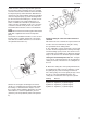
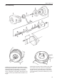
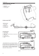
17. Fit the injection pump(s) together with the calculated
shim thickness. Turn the engine so that the cam for the
pump is not in the lifting position. Check that the pump’s
pin locates in the control rod’s groove and that the
pump(s) and the locks markings coincide (see figure).
Check after fitting each pump that the control rod oper-
ates easily.
Tightening torque for the nuts is 20 Nm (14.7 ft.lbs).
Connect the fuel pipe between the pumps and the pipe
from the fuel filter to the injection pump.
NOTE! The hole bolt for the return hose has a smaller
through-flow channel than the others (on later versions it
is marked “Out“)
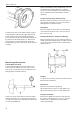
18. Install the feed pump and the fuel filter. Also install
the thermostat housing with the thermostat.
NOTE! Do not forget the lifting eyelet between the fuel
filter and the thermostat housing.