
Technical data

36
Turbo compressor
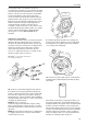
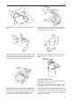
6. Unfasten the four screws which hold the compres-
sion bearing (8). Using a small copper mandrel, tap
out the compression bearing and the bushing (9).
Then remove the circlips (10) inside the bearing hous-
ing and remove the two bearings (11). Remove the
packing ring (12) on the turbine shaft and the two
packing rings (13) on the oil deflector. Clean the parts
carefully.
Measuring and Inspection
Turbine Wheel and Shaft
7. Check that the turbine wheel and shaft are free
from mechanical damage. The vanes must not be
worn or out of shape. Do not try to realign the vanes.
Damaged parts should be replaced.
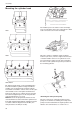
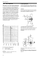
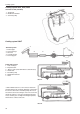
8. Place the shaft on two supports, which should be
under the bearing recesses, and check the throw at
the end of the shaft. The maximum permissible throw
is 0.011 mm (0.00043 in).
9. Check the diameter of the shaft bearing recesses.
The minimum permissible diameter is 7.98 mm
(0.3141 in). Check the width of the shaft piston ring
groove. Maximum permissible width is 1.29 mm
(0.0507 in).
Compressor Housing, Turbine Housing
10. Check that the housings are free from cracks or
other damage caused by excessive wear and tear.
Damaged parts should be replaced.
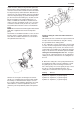
Heat Shield
11. Check that the heat shield is free from damage
caused by wear and tear, heat or corrosion, and re-
place it if necessary.
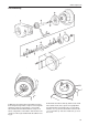
Bushing, Oil Deflector, Compressor Bearing
12. Check that the parts are free from wear and tear
and discolouration. Damaged parts should be replaced
even if the amount of wear and tear is within the per-
mitted tolerances.
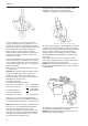
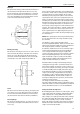
Bushing
13. Check measurement (A), which should not be less
than 4.07 mm (0.16023 in).
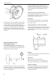
Oil Deflector
14. Check measurements (B) and (C).
(B) should not be more than 1.31 mm (0.05157 in)
(C) should not be more than 1.11 mm (0.04370 in).
Compressor Bearing
15. Check the width of the bearing, and replace it if
the amount of wear and tear is in excess of the per-
mitted tolerance. Minimum permissible width is
3.98 mm (0.15669 in).