DEAR VOLVO OWNER THANK YOU FOR CHOOSING VOLVO We hope that you will enjoy many years of driving pleasure in your Volvo. The car has been designed for the safety and comfort of you and your passengers. Volvo is one of the safest cars in the world. Your Volvo has also been designed to satisfy all current safety and environmental requirements.
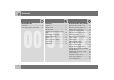
Contents 00 Introduction 01 Safety Introduction ........................................ 6 Volvo Cars and the environment ......... 7 Seatbelts .......................................... Airbag system .................................. Airbags (SRS) ................................... Activating/deactivating the airbag (SRS) ................................................ Side airbags (SIPS bags).................. Inflatable Curtain (IC) ....................... WHIPS....................................
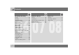
Contents 03 Climate control 04 Interior 05 Locks and alarm General information on climate control .............................................. 72 Manual climate control, A/C.............. 74 Electronic climate control, ECC (option) ............................................. 76 Air distribution .................................. 79 Fuel-driven heater (option ................ 80 Front seats ........................................84 Interior lighting ..................................
Contents 4 06 Starting and driving 07 Wheels and tyres General ............................................ 116 Refuelling........................................ 118 Starting the engine ......................... 119 Keyless drive (option) ..................... 121 Manual gearbox.............................. 122 Automatic gearbox ......................... 124 All-wheel drive ................................ 127 Brake system................................... 128 Stability and traction control system ..
Contents 09 Maintenance and service Volvo service .................................. Self-maintenance ........................... Bonnet and engine compartment .. Diesel.............................................. Oils and fluids ................................ Wiper blades .................................. Battery........................................... Replacing bulbs ............................. Fuses ..............................................
Introduction Introduction Owner’s Manual A good way of getting to know your new car is to read the Owner’s Manual, ideally before your first journey. This will give you the opportunity to familiarise yourself with new functions, to see how best to handle the car in different situations, and to make the best use of all the car’s features.
Introduction Volvo Cars and the environment Volvo Cars’ environmental philosophy Environmental care, safety and quality are the three core values which influence all operations of the Volvo Car Corporation. We also believe that our customers share our consideration for the environment. EPI (Environmental Product Information) is supplied for all Volvo models. You can now compare the environmental impact of different models and engines during the entire lifecycle.
Introduction Volvo Cars and the environment Efficient emission control Your Volvo is manufactured following the concept Clean inside and out – a concept that encompasses a clean interior environment as well as highly efficient emission control. In many cases the exhaust emissions are well below the applicable standards. In addition there is a special radiator coating, PremAir®1, which can convert hazardous ground-level ozone into pure oxygen when the ozone passes the radiator.
Introduction Reducing environmental impact You can help reduce environmental impact, for example, by driving economically, by purchasing eco-labelled car care products and by servicing and maintaining the car according to the instructions in the Owner’s Manual. The following hints will help you to do your bit for the environment: • Decrease fuel consumption by choosing ECO tyre pressure, see page 158. • A roof load and ski box increase wind resistance, leading to significantly higher fuel consumption.
Seatbelts .................................................................................................. Airbag system .......................................................................................... Airbags (SRS) ........................................................................................... Activating/deactivating the airbag (SRS) ........................................................................................................ Side airbags (SIPS bags) .....................
SAFETY 01
01 Safety 01 Seatbelts Always use a seatbelt feed the belt in by hand so that it does not hang lose. WARNING Each belt is intended for one person only. The belt locks and cannot be withdrawn • if it is pulled out too quickly. • during braking and acceleration. • if the car leans heavily. It is important that the belt lies against the body so it can provide maximum protection. Do not lean the backrest too far back. The seatbelt is designed to protect in a normal seating position.
01 Safety Seatbelts Seatbelt reminder Unbelted occupants will be reminded to fasten their seatbelts through an audio and visual reminder. The audio reminder is speed-dependent. The visual reminder is located in the roof console and the combined instrument panel. At low speed, the audio reminder will sound for the first six seconds. Child seats are not covered by the seatbelt reminder system.
01 Safety 01 Seatbelts the vehicle as they drive (which means they must be able to easily operate the foot pedals and steering wheel). Within this context, they should strive to position the seat with as large a distance as possible between their abdomen and the steering wheel. Seatbelt tensioner Label on seatbelts with seatbelt tensioner. 14 All the seatbelts (except the centre rear belt) are equipped with belt tensioners.
01 Safety Airbag system Warning symbol on the combined instrument panel 01 As well as the warning symbol, a message may appear on the information display in appropriate cases. If the warning symbol malfunctions, the warning triangle illuminates and the message SRS AIRBAG SERVICE REQUIRED or SRS AIRBAG SERVICE URGENT appears in the information display. Contact an authorised Volvo workshop urgently. WARNING The airbag system1 is continually monitored by the system control module.
01 Safety 01 Airbags (SRS) Airbag (SRS) on the driver’s side Passenger airbag (SRS) . WARNING To minimise the risk of injury if the airbag deploys, passengers must sit as upright as possible with their feet on the floor and backs against the backrest. Seatbelts must be secured. WARNING The car has an SRS airbag (Supplemental Restraint System) in the steering wheel to supplement the protection afforded by the seatbelt. This airbag is fitted into the centre of the steering wheel.
01 Safety Airbags (SRS) SRS system 01 WARNING Repairs must only be performed by an authorised Volvo workshop. Unauthorised work on the SRS system could cause malfunction and result in serious injury. SRS system, left-hand drive. The system consists of airbags and sensors. A sufficiently violent collision trips the sensors and the airbag(s) are inflated with hot gas. To cushion the impact, the airbag deflates when compressed. When this occurs, smoke escapes into the car. This is completely normal.
01 Safety 01 Airbags (SRS) Location of the passenger airbag in left-hand drive and right-hand drive cars WARNING Never interfere with SRS components in the steering wheel or the panel above the glovebox. Objects and accessories must not be positioned or glued on or near the SRS AIRBAG panel (above the glovebox) or in the area affected by a deployed airbag.
01 Safety Activating/deactivating the airbag (SRS) PACOS (option) Activating/deactivating 01 WARNING Activated airbag (passenger seat): Never place a child in a child seat or on a booster cushion on the front passenger seat when the airbag is activated. This applies to everyone shorter than 140 cm. Deactivated airbag (passenger seat): No one taller than 140 cm should ever sit in the front passenger seat when the airbag is deactivated. Failure to follow the advice given above can endanger life.
01 Safety 01 Activating/deactivating the airbag (SRS) Switch position Switch for SRS in ON position. Switch for SRS in OFF position. ON = Airbag (SRS) activated. With the switch in this position, persons taller than 140 cm can sit in the front passenger seat, but never children in a child seat or on a booster cushion. OFF = Airbag (SRS) is deactivated.
01 Safety Side airbags (SIPS bags) Side airbags – SIPS bags 01 WARNING Do not put objects in the area between the outside of the seat and the door panel, since this area is required by the side airbag. WARNING Use only Volvo genuine car seat covers, or seat covers approved by Volvo. Other seat covers may impede the operation of the side air bags. Child seats and side airbags Side airbag locations.
01 Safety 01 Side airbags (SIPS bags) SIPS bags Driver’s side The SIPS bag system consists of side airbags and sensors. A sufficiently violent collision trips the sensors and the side airbags are inflated. The airbag inflates between the occupant and the door panel and thereby cushions the initial impact while deflating. The side airbag is normally only deployed on the side of the collision.
01 Safety Inflatable Curtain (IC) 01 Properties The inflatable curtain, IC (Inflatable Curtain), is a supplement to the SIPS system. It is fitted in the headlining along both sides of the roof and protects both front and rear seat passengers. The inflatable curtain is activated by sensors in the event of a sufficiently violent collision and the inflatable curtain inflates.
01 Safety 01 WHIPS Protection against whiplash injury – WHIPS The whiplash protection system (WHIPS) consists of energy absorbing backrests and specially designed head restraints for the front seats. The system is actuated by a rearend collision, where the angle and speed of the collision, and the nature of the colliding vehicle all have an influence.
01 Safety WHIPS Do not obstruct the WHIPS system 01 WARNING If a seat has been subjected to extreme forces, such as due to a rear-end collision, the WHIPS system must be checked by an authorised Volvo workshop. Part of the WHIPS system’s protective capacity may have been lost even if the seat appears to be undamaged. Contact an authorised Volvo workshop to have the system checked after even a minor rear-end collision.
01 Safety 01 When the systems deploy System Triggered Seatbelt tensioner In a frontal collision and/or side-impact accident and/or overturning. Airbags (SRS) In a frontal collision1. Side airbags (SIPS) In a side-impact accident1. Inflatable Curtain IC In a side-impact accident1. Whiplash protection WHIPS In a rear-end collision. 1 The bodywork of the car could be greatly deformed in a collision without airbag deployment.
01 Safety Crash mode Driving after a collision If everything seems normal and you have checked for indications of fuel leakage, you may attempt to start the car. Firstly, remove the ignition key and then reinsert it. The car’s electronics will then try to reset themselves to normal mode. Then try to start the car. If CRASH MODE is still shown in the display then the car must not be driven or towed. Even if the car appears to be driveable, hidden damage may make the car impossible to control once moving.
01 Safety Child safety 01 Children should sit comfortably and safely Child seats and airbags The position of a child in the car and the choice of equipment is dictated by the child’s weight and size. For more information see page 30. NOTE Regulations regarding the placement of children in cars vary from country to country. Check what laws apply. Children of all ages and sizes must always sit correctly secured in the car. Never allow a child to sit on the knee of a passenger.
01 Safety Child safety Decal located on instrument panel end face. 01 Decal located on instrument panel end face (Australia only).
01 Safety 01 Child safety Placement of children in the car Weight/age Front seat1 Outer rear seat Centre rear seat <10 kg (0–9 months) Rear-facing child seat, secured with seatbelt and straps. Use a protective cushion between the child seat and the dashboard. L 2: Type approval no. E5 03135 Rear-facing child seat, secured with seatbelt, support legs and straps. L 2: Type approval no. E5 03135 Rear-facing child seat, secured with seatbelt, support legs and straps. L 2: Type approval no.
01 Safety Child safety Integrated booster cushion (option) WARNING 01 Raising the booster cushion Never place a child in a child seat or on a booster cushion in the front seat if the airbag (SRS) is activated. No one shorter than 140 cm should ever sit in the front passenger seat if the airbag (SRS) is activated.1 Failure to follow the advice given above can endanger the life of the child. 1 For information on activated/deactivated airbag (SRS), see page 19.
01 Safety 01 Child safety • the seatbelt is in contact with the child’s body and is not slack or twisted, and that the belt is positioned correctly across the shoulder. • the hip strap is low across the hips for optimum protection. • the seatbelt does not lie across the child’s throat or below the shoulder • Carefully adjust the position of the head restraint to suit the child. Lowering the booster cushion WARNING Repair or replacement should only be performed by an authorised Volvo workshop.
01 Safety Child safety Fitting a child seat Volvo has child safety products that are designed for and tested by Volvo. WARNING Booster cushions/child seats with steel braces or some other design that could rest on the seatbelt buckle’s opening button must not be used, as they could cause the seatbelt buckle to open accidentally. Do not allow the upper section of the child seat to rest against the windscreen.
Overview, left-hand drive cars.................................................................. 36 Overview, right-hand drive cars ............................................................... 38 Driver’s door control panel....................................................................... 40 Combined instrument panel .....................................................................41 Indicator and warning symbols ................................................................
INSTRUMENTS AND CONTROLS 02
02 Instruments and controls Overview, left-hand drive cars 02 36
02 Instruments and controls Overview, left-hand drive cars 1. Steering wheel adjustment 2. Bonnet release 3. Control panel 4. Direction indicators, main beam, trip computer 5. Lighting, fuel filler flap opener 6. Door handle, lock button. 7. Air vents in dashboard 8. Air vent for side window 9. Cruise control 10. Horn, airbag 11. Combined instrument panel 12. Keypad for infotainment system 13. Windscreen wipers and washer, headlamp washers 14. Ignition switch 15. Sunroof controls 16. No function 17.
02 Instruments and controls Overview, right-hand drive cars 02 38
02 Instruments and controls Overview, right-hand drive cars 1. Switch, optional equipment 2. Blind Spot Information System, BLIS 3. Electrical socket, cigarette lighter 4. Parking brake 5. Control panel 6. Glovebox 7. Door handle 8. Air vent for side window 9. Air vents in dashboard 10. Gear lever 11. Climate control 12. Controls for climate control, infotainment system and personal preferences 13. Infotainment system 14. Display for climate control and infotainment system 15. Interior rearview mirror 16.
02 Instruments and controls Driver’s door control panel Driver’s door control panel 02 1. Blocking switch for rear power windows (standard) Electric child locks (option) 2. Power windows 3. Door mirror, left-hand side 4. Door mirrors, setting 5.
02 Instruments and controls Combined instrument panel 02 1. 2. 3. 4. Speedometer. Direction indicators, left. Warning symbol. Information display – The display presents information and warning messages, outside temperature and the time. When the ambient temperature is between +2 C and –5 C, a snowflake symbol appears on the display. This warns of icy roads. The outside temperature gauge may show a slightly high reading after the car has been stationary. 5. Information symbol. 6.
02 Instruments and controls Indicator and warning symbols Functionality check, symbols 02 All indicator and warning symbols1 illuminate when the ignition key is turned to position II before starting. This is to check that the symbols are working. When the engine starts, all the symbols should go out except the handbrake symbol, which extinguishes when the handbrake is released.
02 Instruments and controls Indicator and warning symbols Indicator symbols – left-hand side – Restart the engine. – Drive to an authorised Volvo workshop to have the ABS checked if the symbol remains lit. 3. Rear fog lamp This symbol is lit when the rear fog lamp is on. 02 4. Stability system STC or DSTC For information on the system’s functions and symbols, see page 130. 5. No function 1. Fault in car’s emissions system Drive to an authorised Volvo workshop to have the system checked. 2.
02 Instruments and controls Indicator and warning symbols Indicator symbols – right-hand side 2. Parking brake applied The lamp illuminates when the parking brake is applied. Always pull the parking brake lever to the end position. NOTE 02 The lamp illuminates irrespective of how hard the parking brake is applied. 1. Indicator symbol for trailer This symbol flashes when the direction indicators are used and a trailer is coupled.
02 Instruments and controls Indicator and warning symbols – Stop the car in a safe place and turn off the engine. – Restart the engine. – If both symbols extinguish, continue driving. – If the symbols remain on, check the level in the brake fluid reservoir. See page 187. – If the brake fluid level is normal but the symbols are still lit, the car can be driven, with great care, to an authorised Volvo workshop to have the brake system checked.
02 Instruments and controls Indicator and warning symbols Reminder – doors not closed If one of the doors, the bonnet1 or the tailgate is not properly closed, the driver will be reminded of this. 02 Low speed If the car moves at a speed less than approx. 7 km/h, the information symbol illuminates and DRIVER DOOR OPEN, PASSENGER DOOR OPEN, LEFT REAR DOOR OPEN, BONNET OPEN or RIGHT REAR DOOR OPEN, is shown in the display. Stop the car safely as soon as possible and close the door or bonnet.
02 Instruments and controls Information display Messages When a warning or indicator symbol come, a message appears on the information display. – Press the READ button (1). Switch between messages with the READ button. Fault messages are stored in the memory until the fault is rectified. 02 NOTE If a warning message appears while you are using the trip computer, the message must be read (press READ) before the previous activity can be resumed.
02 Instruments and controls Electrical socket and switches on centre console 12 V electrical socket Cigarette lighter (option) Activate the lighter by pushing in the button. The button pops out when the lighter is hot. Pull out the lighter and light a cigarette on the heated coils. Extra equipment 02 Space for an extra switch for retrofitted equipment. Electrical socket, BLIS and extra equipment The electrical socket can be used for 12 V accessories, such as mobile phone chargers and coolers.
02 Instruments and controls Lighting panel Headlamp levelling The load in the car changes the vertical alignment of the headlamp beam, which could dazzle oncoming motorists. Avoid this by adjusting the height of the beam. – Turn the ignition key to position II. – Turn the headlamp control (2) to one of the end positions. – Roll the control (1) up or down respectively to raise or lower beam alignment. Cars with Bi-Xenon headlamps1 have automatic headlamp levelling, so there is no control (1).
02 Instruments and controls Lighting panel the day and can be controlled manually at night. – Roll the control up or down (3) for brighter or dimmer lighting. Enhanced display lighting 02 To facilitate reading the odometer, trip meter, clock and outside temperature gauge, these illuminate when the car is unlocked and when the key is removed from the ignition switch. The displays extinguish when the car is locked. Fog lamps NOTE Regulations for use of fog lamps vary from country to country.
02 Instruments and controls Left-hand stalk switch Stalk switch positions Short flash sequence – Move the stalk switch up or down to position (1) and release. The direction indicators flash three times and the stalk switch returns to its home position. Switching, main and dipped beam The ignition key must be in position II for main beam to be switched on. – Move the stalk switch towards the steering wheel to the end position (4) and release. – Get out of the car and lock the door.
02 Instruments and controls Left-hand stalk switch Trip computer (option) Functions The trip computer displays the following information: • • • • • • 02 AVERAGE SPEED ACTUAL SPEED MPH1 INSTANTANEOUS AVERAGE KILOMETRES TO EMPTY TANK STC/DSTC, see page 130 AVERAGE SPEED When the ignition is switched off, the average speed is stored and used as the basis of the new value when you continue driving. Reset using the RESET button (C).
02 Instruments and controls Right-hand stalk switch Windscreen wipers Single sweep Raise the stalk switch to make a single sweep. Intermittent wiping The delay between sweeps can be adjusted. Turn the thumbwheel (C) up for a shorter interval between sweeps. Turn it down to increase the delay. Continuous wiping The wipers sweep at normal speed. A. Windscreen and headlamp washers The wipers sweep at high speed. B. Rain sensor – On/Off C. Thumbwheel D.
02 Instruments and controls Right-hand stalk switch Rear window wiper and washer Press the stalk switch forward to initiate rear window washing and wiping. The wiper blade makes several sweeps once washing has finished. The control at the end of the stalk has three positions: 02 Rain sensor (option) – Press the button (B). A display symbol shows that the rain sensor is active. To turn the rain sensor off, either: Intermittent wiping: – Depress the top of the switch.
02 Instruments and controls Cruise control (option) Activating Increasing or decreasing speed Temporary disengagement – Press 0 to disengage the cruise control temporarily. CRUISE will be shown on the combined instrument panel. The speed set earlier is stored in the memory. The cruise control is also temporarily disengaged when: The controls for cruise control are to the left of the steering wheel. Setting the desired speed: – Press the CRUISE button. CRUISE is shown on the combined instrument panel.
02 Instruments and controls Cruise control (option) Return to the set speed –Press this button to resume the previously set speed. CRUISE ON appears on the combined instrument panel. 02 56 Disengaging – Press CRUISE to disengage the cruise control. CRUISE ON goes out on the combined instrument panel.
02 Instruments and controls Steering wheel keypad (option) 02 The four buttons at the bottom of the steering wheel keypad control the radio and the phone. The function of a button depends on which system is active. The steering wheel keypad can be used to scroll between preset stations, change CD tracks and adjust the volume. – Press and hold one of the arrow keys to fast forward/reverse or search for the next station. The phone must be switched on to adjust audio system settings.
02 Instruments and controls Steering wheel adjustment, hazard warning flashers Steering wheel adjustment Hazard warning flashers The steering wheel can be adjusted for both height and reach. Use the hazard warning flashers (all direction indicators flash) when the car is stopped where it could be a traffic hazard or obstruction. Press the button to activate the function. 02 – Pull the lever towards you to release the steering wheel. – Adjust the steering wheel to the position that suits you best.
02 Instruments and controls Parking brake, electrical socket Parking brake (handbrake) – If the vehicle rolls, the parking brake lever must be pulled more firmly. When parking a vehicle always put the gear selector in 1st gear (for manual transmission) or P (for automatic transmission). Electrical socket in the rear seat 02 Parking on a hill If the car is parked facing uphill; turn the wheels away from the kerb. If the car is parked facing downhill; turn the wheels toward the kerb.
02 Instruments and controls Power windows Operation 02 Driver’s door The power windows are operated using the controls in the doors. The ignition key must be in position I and II for the power windows to operate. The windows continue to work for a limited time when the car is stopped and ignition key removed, provided none of the doors is opened. Operate the windows with caution. window will then open or close automatically. If the window is obstructed by an object, the movement will stop.
02 Instruments and controls Power windows Blocking power windows in the rear doors Rear power windows NOTE If the car has electric child safety locks on the rear doors, the light indicates that these are activated. The doors then cannot be opened from the inside. A text message is shown on the display when the electric child safety locks are activated. 02 Front passenger seat Blocking rear power windows and electric child safety locks1.
02 Instruments and controls Rearview and door mirrors Interior rearview mirror Rearview mirror with compass (option on certain markets) Calibrating the compass 02 Bright light from behind could be reflected in the rearview mirror and dazzle the driver. Use dimming when disturbed by light from behind. Dipping 1. Control for dimming 2. Normal position 3. Dimmed position. Automatic dimming (option) Bright light from behind is automatically dimmed by the rearview mirror.
02 Instruments and controls Rearview and door mirrors – Press the button (1) repeatedly until the number for the required magnetic zone (1– 15 ) is shown, refer to the map of magnetic zones for the compass. – Wait until the display returns to showing the character C. – Following which, press and hold the button for 9 seconds and select L for lefthand drive cars and R for right-hand drive.
02 Instruments and controls Rearview and door mirrors Door mirrors Retractable power door mirrors (option) The mirrors can be retracted for parking and driving in narrow spaces. This can be done in ignition position I and II. Retracting the mirrors – Press the L and R button at the same time. – Release the buttons. The mirrors automatically stop in the fully retracted position. 02 IMPORTANT The controls for adjusting the two door mirrors are at the front of the driver’s door armrest.
02 Instruments and controls Rearview and door mirrors Water and dirt-repellent coating (option) The door mirrors are treated with a coating that maintains good rear-view vision despite the rain. The mirrors treated with the water and dirt-repellent coating are marked with a small symbol. For information on how the mirrors should be maintained, see page 173. 02 In certain weather conditions, the function of the dirt-repellent coating is improved if the door mirror defrosters are used, see page 75 or 78.
02 Instruments and controls Power sunroof (option) Open positions From ventilation position to fully open sunroof: – Pull the control rearward to the end position (1) and release. Sliding position 02 Automatic operation – Pull the control past the point of resistance (2) to the rear end position (1) or past the point of resistance (3) to the forward end position (4) and release. The sunroof opens/closes completely. Manual operation The sunroof controls are located in the roof panel.
02 Instruments and controls Power sunroof (option) Closing with remote control or lock button Sunscreen The sunroof features a manual, sliding interior sunscreen. The sunscreen slides back automatically when the sunroof is opened. Grip the handle and slide the screen forwards to close it. Pinch protection 02 The sunroof’s pinch protection function is activated if the hatch is blocked by an object. If blocked, the sunroof will stop and automatically open to the previous position.
02 Instruments and controls Personal preferences 02 Possible settings Climate control settings Personal preferences can be set for some of the car’s functions: the locks, climate control and audio functions. For audio functions, see page 208. Auto blower adjust The fan speed can be set to AUTO mode in cars equipped with ECC: Control panel A. Display B. MENU C. EXIT D. ENTER E. Navigation Use The settings are shown on the display (A). Open the menu to enter settings: Control panel – Press MENU (B).
02 Instruments and controls Personal preferences Automatic locking – doors When the speed of the car exceeds 7 km/h the doors and tailgate can be locked automatically. This function can be turned On/ Off. Pulling the door handle twice unlocks and opens the doors from the inside. Home safe lighting Select the time the car’s lights should remain on when the left-hand stalk switch is pulled back after the ignition key has been removed. The following alternatives are available: 30/60/90 seconds.
General information on climate control ...................................................................................................... 72 Manual climate control, A/C...................................................................... 74 Electronic climate control, ECC (option) ..................................................................................................... 76 Air distribution ..........................................................................................
CLIMATE CONTROL 03
03 Climate control General information on climate control 03 Air conditioning Refrigerant The climate control system cools or heats, and dehumidifies the air entering the passenger compartment. The car is equipped with either manual (A/C ) or electronic climate control (ECC). The air conditioning system contains R134a refrigerant. This refrigerant contains no chlorine, which means that it is harmless to the ozone layer. The system must only be charged with R134a refrigerant.
03 Climate control General information on climate control Air vents in the dashboard ECC (option) Actual temperature The temperature you select corresponds to the physical experience with reference to factors such as air speed, humidity and solar radiation in and around the car. Condensation In warm weather, condensation from the air conditioning system may drip under the car. This is normal. 03 Sensor location • The sun sensor is on the top side of the dashboard.
03 Climate control Manual climate control, A/C Control panel 03 1. 2. 3. 4. 5. 6. 7. 8. Fan Recirculation Defroster Air distribution AC ON/OFF Heated front left seat Heated front right seat Rear window and door mirror defrosters 9. Temperature 74 Functions 1. Fan Increase or decrease the fan speed by turning the knob. If the knob is turned anticlockwise and the fan indicator in the display goes out, the fan and the air conditioning are switched off. The display shows the fan symbol and OFF. 2.
03 Climate control Manual climate control, A/C Timer The timer function minimises the risk of icing, misting and bad air if recirculation is selected. See page 68, for how to activate/deactivate the function. When the Defroster (3) program is selected, recirculation is deactivated. 4. Air distribution The airflow can be distributed to the windows, dashboard vents or floor by pressing the air distribution buttons. 3.
03 Climate control Electronic climate control, ECC (option) Control panel 03 1. 2. 3. 4. 5. 6. 7. 8. 9. AUTO Fan Recirculation/Air quality system Defroster Air distribution A/C – On/Off (ON/OFF) Heated front left seat Heated front right seat Rear window and door mirror defrosters 10. Temperature selector 76 Functions 1. AUTO The AUTO function automatically regulates climate control and maintains the selected temperature.
03 Climate control Electronic climate control, ECC (option) NOTE If the knob is turned anticlockwise and the fan indication on the display goes out, the fan and the air conditioning are switched off. The display shows the fan symbol and OFF. 3. Recirculation Recirculation can be used to shut out bad air, exhaust fumes, etc. from the passenger compartment. The air in the passenger compartment is recirculated, i.e. no outside air is taken into the car when this function is activated.
03 Climate control Electronic climate control, ECC (option) 5. Air distribution The airflow can be distributed to the windows, dashboard vents or floor by pressing the air distribution buttons. 03 A symbol on the display above the climate control panel and an illuminated light in the relevant button indicate which function has been selected. See the table on p. 79. 6. AC – ON/OFF ON: Air conditioning is on. It is controlled by the system’s AUTO function. This way, incoming air is cooled and dehumidified.
03 Climate control Air distribution Air distribution Use: Air distribution Use: Air to windows. Some air flows to the dashboard air vents. The air is not recirculated. Air conditioning is always engaged. To remove ice and misting quickly. Air to the floor and windows. Some air flows to the dashboard air vents. To ensure comfortable conditions and good demisting in cold or humid weather. Air to windscreen and side windows. Some air flows to the dashboard air vents.
03 Climate control Fuel-driven heater (option) General information about heaters 03 Parking on a hill If the car is parked on a steep hill, the front of the car should point downhill to ensure that there is a supply of fuel to the parking heater. WARNING The car must be outdoors when the petrol or diesel heater is used. WARNING Switch off the fuel-driven heater before refuelling. Spilled fuel could be ignited. Check on the information display that the heater is off.
03 Climate control Fuel-driven heater (option) Immediate stop of heater Setting the TIMER AM and PM Clock/timer – Use the thumbwheel (B) to scroll to DIRECT START. – Press RESET (C) to access the options ON and OFF. – Select OFF. For safety reasons, you can only programme times for the following 24 hours, not several days in advance. If the car clock is reset after the heater timers are programmed, the selected times will be cancelled. – Scroll with the thumbwheel to TIMER.
Front seats ...............................................................................................84 Interior lighting ......................................................................................... 86 Storage spaces in the passenger compartment...................................... 88 Rear seat .................................................................................................. 90 Cargo area....................................................................................
INTERIOR 04
04 Interior Front seats Seating position 4. Lumbar support1, turn the wheel, (option on passenger side) 5. Backrest rake: turn the wheel. 6. Control panel for power seat (option). WARNING Adjust the position of the driver’s seat before setting off, never while driving. Check that the seat is locked in position. 04 Lowering the front seat backrest (option) The passenger seat backrest can be folded forward to make room for long loads.
04 Interior Front seats Power seat (option) Memory function Emergency stop If the seat accidentally begins to move, press any of the buttons to stop the function. WARNING Risk of crushing. Make sure that children do not play with the controls. Check that there are no objects in front of, behind or under the seat during adjustment. Ensure that none of the rear seat passengers can be trapped.
04 Interior Interior lighting Reading lamps and interior lighting Cargo area lighting Interior and cargo area lighting are switched on when the tailgate is opened and remain on for 5 minutes. The lighting switches off: • if the tailgate is closed • if switch (2) is set to the Off position. Automatic lighting The passenger compartment lighting is switched on and off automatically when button (2) is in neutral position. 04 Passenger compartment lighting and reading lamps. Reading lamps, rear 1.
04 Interior Interior lighting The passenger compartment lighting can be switched on or off with button (2) within 30 minutes, from the time that the key is turned to position 0, and it then remains on for 5 minutes if it is not switched off. Vanity mirror1 04 The light illuminates automatically when the cover is lifted. 1 Option on certain markets.
04 Interior Storage spaces in the passenger compartment 04 88
04 Interior Storage spaces in the passenger compartment Storage spaces Glovebox 1. Storage pocket (also on front edge of front seat cushions). 2. Compartment in door panel. 3. Ticket clip. 4. Coat hanger, only for light garments. 5. Glovebox. 6. Waste bin (accessory). 7. Storage compartment (e.g. for CD discs) and cup holder1. 8. Bottle holder (option). 9. Storage compartment and cup holder.
04 Interior Rear seat Head restraint, rear Tipping the rear seat backrest The rear seat backrests can be tipped forwards together, or individually, to make it easier to transport long objects. To avoid damaging the seatbelts when folding the backrests up or down, these should be hooked onto the grab handles. NOTE When tipping the rear seat the safety plug for the 12 V socket should be removed and placed in the glovebox to avoid pressure marks in the upholstery.
04 Interior Rear seat NOTE Bottle holder (option) When the backrest has been raised, the red indicator should no longer be showing. If it is, the backrest is not locked in place. WARNING Remember to take down the seatbelts once you have raised the backrest. 04 Lowering the backrest – Pull the lock (2) catch up and forward to release the backrest. A red indicator on the lock catch shows that the backrest is no longer locked in place.
04 Interior Cargo area Safety grille (option) To fold down the grille, do the reverse. Cargo cover A (option) Removing Remove the safety grille as follows: 04 The safety grille is designed to help prevent loads or pets from being thrown forward in the passenger compartment in the event of sudden braking. For safety reasons, the grille must always be correctly fastened and secured.
04 Interior Cargo area Removing the cargo cover: Remove the cargo cover as follows: Cargo cover B (option) – Press the buttons on the cargo cover and pull the end pieces out of the side panels. Release the buttons, lift the cover and remove it from the car. Opening the storage cover – Open the cover by pressing on the cargo cover at the "PUSH" text (see illustration). – Following which, lift up the cover. Closing the storage cover. – Close the cover by lowering it (in slightly open position).
04 Interior Cargo area Removing the cargo cover. – Lift up the front section of the cargo cover, move it backwards and then allow it to hang free. – Move the button forwards, lift up one end of the cargo cover. Repeat on the opposite side. Following which, pull out the cargo cover. 04 Safety net Using the safety net with lowered backrests The safety net can also be used when the backrests are lowered. In this case, use the front attachment points in the roof panel.
04 Interior Cargo area Using the safety net together with the cargo cover Load retaining eyelets Electrical socket in cargo area (option) 04 – Tip the backrests slightly forward to access the safety net cassette. Start with the 40 % section. – Extend the safety net rearward. – Fold the backrests back up. – Hook the net into the attachment points in the roof panel as described for raised backrests. The load retaining eyelets1 are used to fasten straps or nets to anchor items in the cargo area.
04 Interior Cargo area Bag holder (option) 04 The bag holder holds shopping bags in place and prevents them tipping over and spilling their contents. – Open the hatch in the cargo area. – Secure the shopping bags with the strap.
04 Interior 04 97
Remote control with key blade .............................................................. 100 Keyless drive (option) ............................................................................. 104 Locking and unlocking ........................................................................... 107 Child safety locks ................................................................................... 110 Alarm (option).......................................................................................
LOCKS AND ALARM 05
05 Locks and alarm Remote control with key blade Remote control Loss of a remote control The car is supplied with two remote controls which also serve as ignition keys. The remote controls contain detachable metal key blades for mechanical locking/unlocking of the driver’s door and glovebox. If you lose a remote control, take the car and the other remote controls to an authorised Volvo workshop. The code of the missing remote control must be erased from the system as a theft prevention measure.
05 Locks and alarm Remote control with key blade 4. Tailgate — Press the button once to unlock the tailgate only. NOTE The function does not open the tailgate. 5. Panic function — Used to attract attention in an emergency. Press and hold the red button for at least three seconds or press it twice within three seconds to activate the direction indicators and the horn. The function can be turned off with the same button once it has been active for at least 5 seconds.
05 Locks and alarm Remote control with key blade Key blade 05 Active locks 1. Active locks, remote control 2. Active locks, key blade The detachable key blade of the remote control is used to lock or unlock the glovebox or driver’s door (without activating the central locking system). NOTE Using the detachable key blade of the remote control to unlock the driver’s door will trigger the alarm. Switch off the alarm with the remote control. See page 112.
05 Locks and alarm Remote control with key blade Weak remote control battery Replacing the remote control battery When the battery runs down and full functionality cannot be guaranteed, the information symbol and REMOTE BATTERY LOW VOLTAGE appear on the display. – Refit the cover and screw it shut. – Press the key blade back into place. Dispose of the old battery in an environmentally-friendly way.
05 Locks and alarm Keyless drive (option) Keyless lock and ignition system 05 104 The keyless drive system allows the car to be unlocked, driven and locked without the need for a key. You simply need to have the remote control with you in a pocket or a bag. Remote control max. 1.5 m from the car In order to open a door or the tailgate, a remote control must be no more than approx. 1.5 m from the car door handle or tailgate.
05 Locks and alarm Keyless drive (option) • the ignition dial has been turned to position 0 • the READ button has been pressed. Unlocking Never leave any remote control in the car If a remote control with keyless drive function is left in the car, it is made passive when the car is locked. This prevents unauthorised entry. – Open the doors by pulling the relevant handle. – Open the tailgate by pressing under the tailgate opening button and lift the tailgate.
05 Locks and alarm Keyless drive (option) Locking Lock the doors and tailgate as follows: – Push in the lock button on one of the door handles. All doors and the tailgate must be closed before the lock button is pushed in. Otherwise they will not lock. When the car is locked, the lock buttons on the inside of the doors retract. Personal preferences The Keyless Drive system can have personal preferences applied, see page 69.
05 Locks and alarm Locking and unlocking Locking/unlocking the car from outside Unlocking The remote control unlock button can unlock the car in two different ways (select option in personal preferences, see page 69): WARNING Be aware that you can be locked in the car if it is locked from the outside with the remote control. You cannot leave the car using any of the controls inside the car.
05 Locks and alarm Locking and unlocking Locking/unlocking the car from inside All the doors can be locked using the respective lock button. Locking the glovebox Opening the doors When the doors are locked from the inside: – Pull the handle twice to unlock and open the doors. 05 The doors and the tailgate can be locked or unlocked simultaneously using the lock button by the door handle. The glovebox can only be locked and unlocked with the removable key blade in the remote control.
05 Locks and alarm Locking and unlocking Deadlocks When deadlocked, the doors cannot be opened from the inside if they are locked. The deadlocks are activated with the remote control. The deadlocks are set after a 25 second delay after the doors are locked. Temporary deactivation of the deadlocks and any detectors The car can only be unlocked from a deadlock state with the remote control. The doors can also be opened from the outside with the key.
05 Locks and alarm Child safety locks Manual child locks in the rear doors Electric child safety locks and disabling the rear window buttons (option) Press the switch on the driver’s door. A message appears on the information display. To activate the child safety locks: – Turn the ignition key to position I or II. – Press the button. When the light in the button illuminates, the rear power windows and rear doors are locked.
05 Locks and alarm Alarm (option) Alarm system Alarm light on instrument panel When the alarm is armed, it continually monitors all alarm inputs. NOTE The alarm is triggered if: • a door, the bonnet or tailgate opens • a non-approved key is used in the ignition or if an attempt is made to force the lock. • a movement is detected in the passenger compartment (if fitted with a movement detector). • the car is raised or towed away (if fitted with a tilt detector). • a battery cable is disconnected.
05 Locks and alarm Alarm (option) Automatic alarm activation This function prevents you accidentally leaving the car without the alarm on. If none of the doors or the tailgate are opened within two minutes of disarming the alarm (and the car has been unlocked with the remote control), the alarm is automatically rearmed, and the car is locked at the same time. – Open the driver’s door with the key blade. The alarm is triggered and the siren sounds. – Insert the remote control into the ignition switch.
05 Locks and alarm Alarm (option) Testing the alarm system Testing the movement detector in the passenger compartment – Open all the windows. – Arm the alarm. Arming the alarm is confirmed by the light flashing slowly. – Wait 30 seconds. – Test the movement detector in the passenger compartment, such as by lifting out a bag from a seat. A siren should sound and all direction indicators should flash. – Deactivate the alarm by unlocking the car with the remote control. – Arm the alarm.
General.................................................................................................... 116 Refuelling ............................................................................................... 118 Starting the engine................................................................................. 119 Keyless drive (option) ............................................................................. 121 Manual gearbox ................................................................
STARTING AND DRIVING 06
06 Starting and driving General Economical driving Driving economically means driving smoothly while thinking ahead and adjusting your driving style and speed to the prevailing conditions. 06 • Get the engine warmed up as soon as possible. • Do not let the engine idle, but drive at light loads as soon as it is possible. • A cold engine consumes more fuel than a warm one. • Avoid braking too hard. • Do not drive with unnecessary loads in the car. • Do not use winter tyres when the roads are dry.
06 Starting and driving General Clean the electric contacts of the electric engine block heater and trailer coupling after driving in water and mud. IMPORTANT Do not let the car stand with water over the sills for any long period of time. This could cause electrical malfunctions. In the event of stalling in water, do not try to restart. Tow the car out of the water. Do not overload the battery The electrical functions in the car load the battery to varying degrees.
06 Starting and driving Refuelling Opening the fuel filler flap 2. Turn past the resistance until it comes to a stop. 3. Take out the cap. 4. Hang up the cap on the inside of the fuel filler flap. NOTE Put the petrol cap back after refuelling. Turn until one or more clear clicks are heard. Filling up with fuel Do not overfill the tank but fill until the pump nozzle cuts out. Switch off the fuel-driven heater before refuelling.
06 Starting and driving Starting the engine Before starting the engine Starting the engine – Apply the parking brake. Automatic gearbox – Gear selector in position P or N. Manual gearbox Put the gear lever in neutral and hold the clutch pedal fully depressed. This is particularly important in very cold conditions. WARNING Never remove the ignition key from the steering lock while driving or when the car is being towed.
06 Starting and driving Starting the engine symbol on the dashboard illuminates, and the message SOOT FILTER FULL SEE MANUAL is shown on the dashboard display. Start regeneration of the filter by driving the car until the engine reaches normal operating temperature, preferably on a main road or motorway. The car should then be driven for approximately 20 minutes more. When regeneration is complete the message is cleared automatically. IMPORTANT If the filter fills up it may be incapable of functioning.
06 Starting and driving Keyless drive (option) General Starting the car Starting with the remote control – Depress the clutch pedal (cars with manual gearbox) or brake pedal (cars with automatic gearbox). Petrol engine – Press in and turn the ignition dial to position III. Diesel engine 1. First turn the ignition dial to position II and wait until the diesel indicator symbol in the combined instrument panel goes out, see page 43. 2. Following which, turn the ignition dial to position III.
06 Starting and driving Manual gearbox 06 Gear positions, five-speed Reverse gear inhibitor, five-speed Gear positions, six-speed (petrol) Depress the clutch pedal fully with each gear change. Remove your foot from the clutch pedal between gear changes! Follow the appropriate shifting pattern. Only engage reverse gear when the car is stationary. To engage reverse gear, the gear lever must first be put in position N.
06 Starting and driving Manual gearbox Reverse gear inhibitor, six-speed (petrol) Only engage reverse gear when the car is stationary. NOTE Reverse gear is electronically blocked if the car is travelling faster than approx. 20 km/h. Gear positions, six-speed (diesel)1 Depress the clutch pedal completely for each gear change. Remove your foot from the clutch pedal between gear changes. Follow the indicated gear pattern. For optimum fuel economy use the highest possible gear as often as possible.
06 Starting and driving Automatic gearbox Cold start Safety systems When starting in low temperatures, the gear changes can sometimes feel hard. This is due to the gearbox oil’s viscosity at low temperatures. To minimise engine emissions, the gearbox shifts up later than normal when the engine is started at low temperatures.
06 Starting and driving Automatic gearbox Mechanical gear selector inhibitor Automatic gear positions The gearbox is mechanically blocked when P position is engaged. Always apply the parking brake when parking the car. R – Reverse The car must be stationary when R is selected. N – Neutral N is the neutral position. No gear is engaged and the engine can be started. Apply the parking brake when the car is stationary with the gear selector in position N.
06 Starting and driving Automatic gearbox Manual positions To move from the automatic driving position D to a manual position, move the gear selector to position M. To go from position M to the automatic driving position D, move the selector to position D. While driving The manual gearshift mode can be selected at any time while driving. The engaged gear is locked until you choose another gear.
06 Starting and driving All-wheel drive All-wheel drive – AWD All-wheel drive is always engaged. All-wheel drive means that all four road wheels are driven at the same time. Power is automatically distributed between front and rear wheels. An electronically controlled clutch system distributes the power to the pair of wheels that grips best. This provides the best traction and prevents wheel spin. Under normal driving conditions, the majority of power is transmitted to the front wheels.
06 Starting and driving Brake system Brake servo If the car is rolling or is being towed with the engine turned off, the brake pedal must be pressed about five times harder than when the engine is running. If the brake pedal is pressed when the engine is started, you will feel the pedal drop. This is normal and due to the brake servo becoming active. This may be more noticeable if the car has emergency brake assistance (EBA). WARNING The brake servo only works when the engine is running.
06 Starting and driving Brake system Emergency brake assistance – EBA In case of sudden braking, full-strength braking is provided instantaneously. The EBA function senses when heavy braking is underway by registering how quickly the brake pedal is depressed. Continue braking without easing off on the brake pedal. The function is suspended when the pressure on the brake pedal eases. This function is always active and cannot be disengaged.
06 Starting and driving Stability and traction control system General The Dynamic Stability and Traction Control system (STC/DSTC) improves the car’s traction and helps the driver to avoid skidding. Traction control system The function is active at low speed and transfers power from the driving wheel that is spinning to the one that is not. Reduced operation A pulsing sound may be noticed during braking or acceleration when the system is in action. The car may accelerate more slowly than expected.
06 Starting and driving Stability and traction control system DSTC ON means that the system function is unchanged. DSTC SPIN CONTROL OFF means that system operation is reduced. – Press and hold RESET (B) until the STC/ DSTC menu is changed. At the same time the symbol illuminates as a reminder that the system has been reduced. The system remains reduced until the engine is next started. WARNING ANTI-SKID SERVICE REQUIRED means that the system has been disabled due to a fault.
06 Starting and driving Parking assistance (option) General 1 Function The system is activated automatically when the car is started and the text message Park Assist active, Exit to deactivate is shown on the audio system display. Parking assistance is active at speeds below 15 km/h. The system is deactivated at higher speeds. The system is reactivated when the speed falls below 10 km/h again. The frequency of the signal increases as you come closer to an object in front of or behind the car.
06 Starting and driving Parking assistance (option) WARNING Cleaning the sensors Some sources may deceive the system with false signals. Examples of such sources include horns, wet tyres on asphalt, pneumatic brakes and motorcycle exhaust pipes. Ice and snow covering the sensors may also cause false warning signals. Activating/deactivating Parking assistance can be deactivated by pressing EXIT on the control panel, see page 68.
06 Starting and driving Blind Spot Information System (BLIS, option) General attention to vehicles moving in the same direction in the so-called "blind spot". Blind spots The system is designed to work most effectively when driving in dense traffic on multilane highways. BLIS is based on digital camera technology. The cameras (1) are located under the door mirrors. When a camera has detected a vehicle inside the blind spot zone the indicator lamp (2) illuminates with a constant glow.
06 Starting and driving Blind Spot Information System (BLIS, option) IMPORTANT The lenses are electrically heated to melt ice or snow. If necessary, brush snow away from the lenses. When BLIS operates The system operates when the car is driven at a speed above 10 km/h. Overtaking The system is designed to react if you overtake another vehicle at a speed of up to 10 km/h faster than the other vehicle.
06 Starting and driving Blind Spot Information System (BLIS, option) Activating/deactivating READ button to clear the text message. For more information on messages, see page 47. BLIS system message Text on the display Button for activating/deactivating. 06 BLIS is activated when the engine is started. The indicator lamps in the door panels flash three times when BLIS is activated. The system can be deactivated/activated by pressing BLIS.
06 Starting and driving Towing and recovery Never tow the car to bump start it Jump start the car with a donor battery if the battery is flat and the engine does not start. Do not bump start the car. IMPORTANT Bump starting the car can damage the catalytic converter. Towing Find out the highest legal speed for towing before towing the car. – Turn the ignition switch to position II and unlock the steering lock so that the car can be steered, see page 120.
06 Starting and driving Towing and recovery 2. Release the cover (1) on the bumper with a screwdriver or coin in the bottom edge. 3. Screw in the towing eye (3) firmly, right up to the flange. Use the wheel wrench to tighten the towing eye. 4. After use, unscrew the towing eye and return it in the cargo area. Refit the cover on the bumper. IMPORTANT The towing eye is only designed for towing on roads, not for pulling the car unstuck or out of a ditch. Call a recovery service for assistance.
06 Starting and driving Start assistance Starting with a donor battery – – – – – If the battery in the car has become flat, you can "borrow" electric current from either a separate battery or the battery in another car. Always make sure the crocodile clips on the jump leads are attached securely to eliminate sparks during the start attempt. When jump starting the car, the following steps are recommended to avoid risk of explosion: – ensure that the cars do not touch one another.
06 Starting and driving Driving with a trailer General The load capacity is affected by extra accessories mounted on the car, such as a towbar, load carriers, space box, the passengers’ combined weight etc. as well as the load on the towball. The load capacity of the car is reduced by the number of passengers and their weight. If the towing bracket is fitted by an authorised Volvo workshop, then the car is delivered with the necessary equipment for driving with a trailer.
06 Starting and driving Driving with a trailer Automatic gearbox, driving with a trailer Diesel 1.6D engine with manual gearbox, driving with a trailer Parking on a hill 1. Apply the parking brake (handbrake). 2. Move the gear selector to parking position P. If the car is driven with a major load in a hot climate, the engine cooling fan can be replaced with one of a greater capacity than the standard model. Check with your nearest Volvo dealer regarding the options for your car. Starting on a hill 1.
06 Starting and driving Towing equipment Towbars Trailer cable The towball must be cleaned and greased regularly. If a towball hitch with vibration damper is used, it is not necessary to grease the towball. If the car is equipped with a detachable towbar, the towball mounting instructions must be followed carefully, see page 144. WARNING Be sure to attach the trailer’s safety cable to the correct place.
06 Starting and driving Towing equipment Specifications Dimensions for mounting points (mm) A B Fixed towbar standard 1104 90 Fixed towbar with Nivomat 1100 96 Detachable towbar standard 1104 90 Detachable towbar with Nivomat 1100 C D E F G H I J K 100 140 06 113 964 482 40 141 542 150 63 96 1 Side member 2 Ball centre 143
06 Starting and driving Detachable towbar Fitting the towball – Remove the guard plug. 06 144 – Ensure that the mechanism is in the unlocked position by turning the key clockwise. – Check that the indicator window (3) shows red. If the window does not show red, press in (1) and turn the locking wheel anticlockwise (2) until you hear a click.
06 Starting and driving Detachable towbar – Insert the towball section until your hear a click. – Check that the indicator window shows green. – Turn the key anticlockwise to the locked position. Remove the key from the lock.
06 Starting and driving Detachable towbar NOTE 06 146 Check that the towball section is secure by pulling it up, down and back. If the towball section is not fitted correctly then it must be removed and refitted in accordance with the previous steps NOTE The trailer’s safety cable must be attached to the attachment on the towbar.
06 Starting and driving Detachable towbar Removing the towball – Insert the key and turn it clockwise to the unlocked position. – Push in the locking wheel (1) and turn it anticlockwise (2) until you hear a click. – Turn the locking wheel down fully, until it comes to a stop. Hold it in this position while pulling the towball rearward and upward.
06 Starting and driving Detachable towbar – Insert the guard plug.
06 Starting and driving Loading General The load capacity is affected by extra accessories mounted on the car, such as a towbar, load carriers, space box, the passengers’ combined weight etc. as well as the load on the towball. The load capacity of the car is reduced by the number of passengers and their weight. For information on permitted weights, see page 233. WARNING The car’s driving characteristics change depending on how heavily it is loaded and how the load is distributed.
06 Starting and driving Adjusting headlamp pattern Correct light pattern for left or righthand traffic A. Headlamp pattern for left-hand traffic. B. Right-hand traffic. 06 150 The headlamps’ projection can be adjusted to avoid dazzling other motorists. The correct pattern will also better illuminate the verge. Halogen headlamps Bi-Xenon headlamps The headlamp control should be in position (A) for left-hand traffic and position (B) for right-hand traffic.
06 Starting and driving 06 151
General................................................................................................... Tyre pressure .......................................................................................... Warning triangle and spare wheel.......................................................... Changing wheels.................................................................................... Emergency puncture repair ....................................................................
WHEELS AND TYRES 07
07 Wheels and tyres General Driving characteristics and tyres Speed ratings New tyres The tyres greatly affect the car’s driving characteristics. The type of tyre, dimensions, tyre pressure and speed rating are important for how the car performs. The car has "Whole Vehicle Type Approval", which means that dimensions and speed ratings must not differ from those specified on the vehicle’s registration document.
07 Wheels and tyres General More even wear and maintenance Tyres with tread wear indicators Tread wear indicators are narrow treadless bands across the width of the tread. On the side of the tyre are the letters TWI (Tread Wear Indicator). When the tyre’s tread depth is down to 1.6 mm, the tread depth will be level in height with the tread wear indicators. Change to new tyres as soon as possible. Remember that tyres with little tread depth provide very poor grip in rain and snow.
07 Wheels and tyres General IMPORTANT Use Volvo genuine snow chains or equivalent chains designed for the car model, and tyre and rim dimensions. Consult an authorised Volvo workshop Rims and wheel nuts 90 Nm. Check the torque with a torque wrench. IMPORTANT The wheel nuts should be tightened to 90 Nm. Overtightening can damage the nuts and the bolts. Steel rims – standard wheel nuts (1) Steel rims are normally mounted with the standard wheel nuts, but the bulge acorn variety may also be used.
07 Wheels and tyres General Spare wheel Temporary Spare Summer and winter wheels The spare wheel1 is only intended to be used for the short time it takes to get the ordinary wheel replaced or repaired. Replace the spare wheel as soon as possible with a normal wheel. The car’s handling may be altered by the use of the spare wheel. If the tyre is mounted incorrectly, the car’s braking characteristics and capacity to force rain, snow and slush out of the way are adversely affected.
07 Wheels and tyres Tyre pressure Recommended tyre pressure Checking the tyre pressure Check the tyre pressure regularly. NOTE Tyre pressure decreases over time, this is a natural phenomenon. Tyre pressure also varies depending on ambient temperature. Even after several kilometres of driving the tyres warm up and the pressure increases, so air must not be released if the pressure is checked when the tyres are warm, while the pressure must be increased if it is too low.
07 Wheels and tyres Tyre pressure Tyre pressure table Speed (km/h) Load, 1-3 persons Front (kPa) Rear (kPa) Max. load Front (kPa) Rear (kPa) Variant Tyre size 1.6 1.8 2.0 1.
07 Wheels and tyres Warning triangle and spare wheel Warning triangle Follow the regulations for the use of a warning triangle 1. Place the warning triangle in a suitable place with regard to the traffic. 07 – Undo the case containing the warning triangle, it is attached with Velcro. Take the warning triangle out of the case. – Lower the warning triangle’s support legs. Ensure the warning triangle and its case are properly secured in the cargo area after use. 1 Certain 160 markets.
07 Wheels and tyres Changing wheels Removing wheels Set up the warning triangle if a wheel must be replaced at a busy location. Make sure that the car and jack are on a firm horizontal surface. – Take out the spare wheel, jack and wheel wrench, which are found under the carpet in the cargo area. – Apply the parking brake and engage first gear, or position P if the car has an automatic gearbox. – Place chocks in front of and behind the wheels which will remain on the ground.
07 Wheels and tyres Changing wheels Fitting the wheel – Clean the contract surfaces on the wheel and hub. – Put on the wheel. Tighten the wheel nuts. – Lower the car so that the wheel cannot rotate. – Tighten the wheel nuts crosswise. It is important that the wheel nuts are tightened properly. Tighten to 90 Nm. Check the torque with a torque wrench. – Put on the wheel cover (steel rim). WARNING Never crawl under the car when it is raised on the jack.
07 Wheels and tyres Emergency puncture repair General Cars which do not have a spare wheel are instead equipped with an emergency puncture repair kit. This kit can be used to both seal the puncture and to check and adjust the tyre pressure. The kit consists of an electric air compressor and an integrated canister with sealing liquid. NOTE The jack is an option on cars equipped with emergency puncture repair kit.
07 Wheels and tyres Emergency puncture repair tures in the wall of the tyre. Do not seal tyres with the emergency puncture repair kit if they have larger slits, cracks, irregularities or similar damage. The emergency puncture repair kit with compressor and tools are found under the floor in the cargo area. 12 V sockets for the compressor are located by the centre console in the front, by the rear seat and in the cargo area. Choose the electrical socket that is nearest the punctured tyre.
07 Wheels and tyres Emergency puncture repair Inflating tyres Set up the warning triangle if a tyre must be inflated in an area close to traffic. – Ensure that the orange switch (2) is in position 0 and take out the lead (5) and air hose (4) from the side compartment (3). – Screw the air hose’s valve connection to the bottom of the thread on the tyre’s air valve. – Connect the lead (5) to one of the car’s 12 V sockets. – Start the engine. The car must be in a wellventilated place.
07 Wheels and tyres Emergency puncture repair Sealing punctured tyres Set up the warning triangle if emergency tyre repairs must be carried out in an area where there is other traffic. 07 166 – Remove the decal (1) regarding the highest permitted speed from the emergency puncture repair kit and stick it on the steering wheel where it can be clearly seen by the driver. – Ensure that the orange switch (2) is in position 0 and take out the lead (5) and air hose (4) from the side compartment (3).
07 Wheels and tyres Emergency puncture repair WARNING Never stand next to the tyre when the compressor is running. Be particularly observant of the tyre walls. If cracks, irregularities or other damage appears, turn off the compressor immediately. Under these circumstances your journey should not continue. Contact an authorised tyre centre. – Undo the air hose (4) from the air valve and put the dust cap back on. Unplug the lead (5) from the electrical socket.
07 Wheels and tyres Emergency puncture repair Changing the sealing fluid canister The canister of sealing fluid should be changed before the best-before date has expired, see date label (1), or after the tyre has been sealed. After use, the canister (6) with holder (8) and air hose (10) should be changed. 07 This change can be carried out by an authorised Volvo workshop or following the instructions. IMPORTANT Read the safety instructions on the bottom of the canister.
07 Wheels and tyres Emergency puncture repair Changing the canister and hose after use – Undo the two screws (2) on the orangecoloured case (3). – Remove the speed label (4) and date label (1), and open the safety catch (5). Loosen the case (3) and take it off. – Push down the button (8) while turning the canister (6) and the holder (9) clockwise. Remove them. – Pull out the air hose (10). – Wipe off remaining sealing fluid with a rag or scrape it away if it is has already dried. – Fit a new air hose (10).
Cleaning ................................................................................................. 172 Touching up paintwork ........................................................................... 175 Rustproofing ..........................................................................................
CAR CARE 08
08 Car care Cleaning Washing the car Wash the car as soon as it becomes dirty. Use car shampoo. Dirt and road salt can lead to corrosion. • Do not park the car in direct sunshine. Washing a car with hot paintwork can cause permanent paintwork damage. Wash the car in a car wash with waste water separator. • Thoroughly rinse dirt off the underbody of the car. • Rinse the entire car to remove loose dirt.
08 Car care Cleaning Polishing and waxing Polish and wax the car if the paintwork is dull or to give the paintwork extra protection. The car does not need to be polished until it is at least one year old. However, the car can be waxed during this time. Do not polish or wax the car in direct sunlight. Wash and dry the car thoroughly before you begin polishing or waxing. Clean off asphalt and tar stains using Volvo tar remover or white spirit.
08 Car care Cleaning IMPORTANT Note that materials that moult (new jeans, suede garments etc.) may discolour the upholstery material. To achieve best results Volvo recommends cleaning and application of the protective cream two to four times per year. Ask your Volvo dealer about Volvo’s Leather Care product 08 174 Washing instructions for leather upholstery – Pour the leather cleaner on the dampened sponge and squeeze out a strong foam. – Work the dirt away with gentle circular movements.
08 Car care Touching up paintwork Paintwork Stone chips and scratches Paint is an important part of the car’s rustproofing and should therefore be checked regularly. To avoid the onset of rust, damaged paintwork must be rectified immediately. The most common types of paintwork damage are stone chips, scratches, and marks on the edges of wings and doors. Colour code Before touching up paintwork, the car must be clean and dry and at a temperature above 15 C.
08 Car care Rustproofing Inspection and maintenance Your car received a thorough and complete rustproofing at the factory. Parts of the body are made of galvanised sheet metal. The underbody is protected by a wear-resistant anti-corrosion compound. And, a thin, penetrating rustproofing fluid was sprayed into the members, cavities and closed sections. Maintain the car’s rustproofing. • Keep the car clean. Hose down the underbody.
08 Car care 08 177
Volvo service .......................................................................................... Self-maintenance ................................................................................... Bonnet and engine compartment .......................................................... Diesel ..................................................................................................... Oils and fluids ........................................................................................
MAINTENANCE AND SERVICE 09
09 Maintenance and service 09 Volvo service Volvo service programme Installing accessories Before the car left the factory, it was thoroughly test driven. It was checked again in accordance with Volvo Car Corporation regulations before it was handed over to you. The incorrect connection and installation of accessories can negatively affect the car’s electrical system. Certain accessories only function when the appropriate software has been programmed into the car’s electrical system.
09 Maintenance and service Self-maintenance Before starting work on the car Battery Check that the battery cables are correctly connected and tightened. Never disconnect the battery when the engine is running (e.g. if replacing the battery). Never use a quick charger to charge the battery. The battery cables must be disconnected when charging the battery. The battery contains acid that is both corrosive and toxic. Handle the battery in an environmentally-suitable way. Let your Volvo dealer assist you.
09 Maintenance and service 09 Bonnet and engine compartment Opening the bonnet – Pull the handle on the far left under the dashboard. You will hear when the catch releases. – Insert your hand under the centre of the front edge of the bonnet and press the safety catch to the right. – Open the bonnet. WARNING Check that the bonnet locks properly when closed. Engine compartment 1. Washer fluid reservoir (4-cyl.) 2. Coolant expansion tank 3.
09 Maintenance and service Diesel Fuel system Diesel must fulfil the EN 590 or JIS K2204 standards. Diesel engines are sensitive to contaminants , such as high volumes of sulphur particles for example. Only use diesel fuel from a well-known producers. Never use diesel of dubious quality. At low temperatures (–40 C to –6 C), a paraffin precipitate may form in the diesel fuel, which can lead to ignition problems.
09 Maintenance and service 09 Oils and fluids Engine compartment decal for oil grade Checking the engine oil and oil filter Volvo recommends oil products. Change the oil and oil filter in accordance with the intervals specified in the Service and Warranty Booklet. IMPORTANT Dipstick, petrol engines IMPORTANT Always use oil of the prescribed grade, see the engine compartment decal. Check the oil level frequently and change the oil regularly.
09 Maintenance and service Oils and fluids Checking the oil level in a new car is especially important before the first scheduled oil change. The Service and Warranty Booklet specifies the odometer readings for oil changes. Checking the oil Volvo recommends checking the oil level every 2 500 km. The most accurate measurements are made on a cold engine before starting. The measurement will be inaccurate if taken immediately after the engine is switched off.
09 Maintenance and service 09 Oils and fluids Washer fluid, topping up Add washer antifreeze during the winter so that the fluid does not freeze in the pump, reservoir and hoses. Checking and topping up the coolant NOTE Mix the washer antifreeze and water before filling the reservoir. Location of washer fluid reservoir1. The windscreen and headlamp washers share a common reservoir. See capacities on page 241. 1. Filler cap on 4-cylinder engines and diesel. 2. Filler cap on 5-cylinder engines.
09 Maintenance and service Oils and fluids Check the coolant regularly The level should lie between the MIN and MAX marks on the expansion tank. If the system is not filled sufficiently, high local temperatures could occur, causing a risk of damage (cracks) in the cylinder head. Top up the coolant when the level falls to the MIN mark. Checking and topping up the brake and clutch fluid 09 braking, such as driving in mountains or tropical climates with high humidity.
09 Maintenance and service 09 Oils and fluids Checking and topping up the power steering fluid NOTE Check the level frequently. The fluid does not require changing. For capacities and recommended fluid grade, see page 237. If a fault should arise in the power steering system or if the car is without power and must be towed, it can still be steered. However the steering will be much heavier than normal and it will require more effort to turn the wheel.
09 Maintenance and service Wiper blades Changing the wiper blades NOTE The wiper blades are different lengths. The blade on the driver’s side is longer than the blade on the passenger side. 09 Changing the rear window wiper blade – Fold out the wiper arm. – Detach the wiper blade by pulling it towards the rear window. – Press home the new wiper blade. Check that it is securely fitted. – Lower the wiper arm. – Turn up the wiper arm.
09 Maintenance and service 09 Battery Battery care WARNING Batteries can generate oxyhydrogen gas, which is highly explosive. A spark, which can be generated if you connect the jump leads incorrectly, is sufficient to make the battery explode. The battery also contains sulphuric acid, which can cause serious burns. If the acid comes into contact with eyes, skin or clothing, flush with large quantities of water. If acid splashes into the eyes, seek medical advice immediately.
09 Maintenance and service Battery Symbols on the battery Risk of explosion. 09 Changing the battery Use protective goggles Further information in the Owner’s Manual. Store the battery out of the reach of children. The battery contains corrosive acid. Avoid sparks and naked flames. Removing the battery – Switch off the ignition and remove the key. – Wait at least 5 minutes before touching any electrical terminals.
09 Maintenance and service 09 Replacing bulbs General Changing front bulbs All bulb specifications are given on page 247.
09 Maintenance and service Replacing bulbs Dipped beam Removing the cover and bulb: – Remove the entire lamp housing. – Bend aside the catches and remove the cover. – Unplug the connector from the bulb. – Release the spring clip that secures the bulb. First, press it to the left to release it, then out and down. – Pull out the bulb. – Refit the lamp housing. 09 Main beam Fitting a new bulb – Fit the new bulb. It can only be fitted in one position.
09 Maintenance and service 09 194 Replacing bulbs Position/parking lamps Direction indicators Side marker lamps – Pull out the bulb holder with a pair of pliers. Do not pull out the bulb holder by pulling the electrical cable. – Replace the bulb. – Press the bulb holder back into place. It can only be fitted in one way. – Twist the bulb holder anticlockwise and remove it. – To remove the bulb from the bulb holder, press the bulb in and turn it anticlockwise.
09 Maintenance and service Replacing bulbs Fog lamps Removing the bulb holder 09 – Press the bulb holder into place and refit the cover (A or B). NOTE If the error message BULB FAILURE/ CHECK STOP LAMP remains after a faulty bulb has been replaced then consult an authorised Volvo workshop. – Switch off all lights and turn the ignition key to position 0. – Remove the panel from around the lamp housing. – Remove the two Torx screws securing the lamp housing and take out the lamp housing.
09 Maintenance and service 09 Replacing bulbs Location of the bulbs in the rear light cluster Bulb holder 1. 2. 3. 4. 5. 196 Brake light Position/parking lamps Direction indicators Rear fog lamp (one side) Reversing lamp Number plate lighting Courtesy lighting – Switch off all lights and turn the ignition key to position 0. – Remove the screws with a screwdriver. – Detach the lens carefully. – Replace the bulb. – Refit and screw in the lens.
09 Maintenance and service Replacing bulbs Courtesy lighting Vanity mirror lighting – Insert a screwdriver and gently turn so that the lamp housing comes loose. – Remove the blown bulb. – Fit a new bulb. Removing the mirror glass: – Insert a screwdriver underneath the lower edge, in the centre. Carefully prise up the lug on the edge. – Insert the screwdriver under the edge on both the left and right side (at the black rubber points) and carefully prise so that the lens releases at the lower edge.
09 Maintenance and service 09 Fuses General Changing All electrical functions and components are fused to protect the car’s electrical system from damage by short circuiting and overloading. If an electrical component or function does not work, it may be because the component’s fuse was temporarily overloaded and blew. The fuses are in two different locations in the car: – Look in the fuse diagram to locate the fuse. – Pull out the fuse and check from the side to see whether the curved wire has blown.
09 Maintenance and service Fuses 09 Relay/fuse box in the engine compartment The fuse box has 36 fuse positions. Be sure to replace a blown fuse with a new fuse of the same colour and amperage. • 19 —36 are of the "Mini Fuse" type. • Fuses 7 —18 are of the "JCASE" type and should be replaced by an authorised Volvo workshop. • Fuses 1 —6 are of the "Midi Fuse" type and may only be replaced by an authorised Volvo workshop. On the inside of the cover are tweezers to assist removing and fitting fuses.
09 Maintenance and service 09 Fuses 1. 2. 3. 4. 5. 6. Radiator fan .............................................................................. 50 A Power steering (not 1.6 l engine) ........................................ 80 A Supply to passenger compartment fuse box ...................... 60 A Supply to passenger compartment fuse box ...................... 60 A Climate control element, additional heater PTC (option) ..... 80 A Glow plugs (4-cyl. diesel) ..............................................
09 Maintenance and service Fuses 09 24. Heated fuel filter, PTC element oil trap (5-cyl. diesel) ..................................................................... 20 A 25. Reserve ...................................................................................26. Ignition switch ................................................................... 15 A 27. A/C compressor ................................................................ 10 A 28. Reserve .................................................
09 Maintenance and service 09 Fuses Relay/fuse box in the passenger compartment The fuse box has 50 fuse positions. The fuses are located under the glovebox. The box also provides space for several spare fuses. Tools for fuse replacement are located in the relay/fuse box in the engine compartment, see page 199. Changing fuses: – Remove the trim concealing the fuse box by pressing in the pin in the centre of the clips (1) about one cm and then withdrawing the clips.
09 Maintenance and service Fuses 37. Reserve ...................................................................................38. Reserve ...................................................................................39. Reserve ...................................................................................40. Reserve ...................................................................................41. Reserve ...................................................................................42.
09 Maintenance and service 09 Fuses 60. Seat heating (driver’s side)................................................. 15 A 61. Seat heating (passenger side) ............................................ 15 A 62. Sunroof ............................................................................ 20 A 63. Supply to rear right door .................................................... 20 A 64. Audio system, RTI (option) ................................................... 5 A 65. Infotainment system ...........
09 Maintenance and service 09 205
General ................................................................................................... 208 Audio functions ...................................................................................... 209 Radio functions ...................................................................................... 211 CD functions .......................................................................................... 215 Menu structure – audio system ................................................
INFOTAINMENT SYSTEM 10
10 Infotainment system General Infotainment system 10 to be active until the key is removed from the ignition switch. The audio system is then started automatically the next time the key is turned to position I. Menus Some infotainment system functions are controlled via a menu system. The current menu level is shown at the top right of the display. Menu options are shown in the middle of the display. Infotainment is a system that integrates the audio system and the phone1.
10 Infotainment system Audio functions Audio controls Audio source selection Repeatedly pressing AM/FM switches between FM1 , FM2 and AM . Repeatedly pressing MODE switches between CD and AUX. AUX1 The AUX input can be used for connecting an MP3 player for example. 10 – Set the audio system in AUX mode using MODE. – Press MENU and then ENTER. – Scroll to AUX input Volume and press ENTER. – Turn TUNING or press right/left on the navigation button. Audio settings 1. VOLUME – Knob 2.
10 Infotainment system Audio functions 10 • CENTER 1 – Centre speaker level. Three channel stereo or Pro Logic II must be activated before adjustment is possible. See page 210. • SURROUND 1 – Surround sound level. Pro Logic II must be activated before adjustment is possible. See page 210. Activating/deactivating the subwoofer – Press MENU and then ENTER. – Scroll to Audio settings and press ENTER. – Scroll to Subwoofer and press ENTER.
10 Infotainment system Radio functions Radio controls Manual tuning – Select wavelength using AM/FM (1). – Adjust the frequency by turning TUNING (3). Tune into a station with a long press (left or right) on the navigation button or by using the steering wheel keypad: – Hold the right or left side of the navigation button depressed until the desired frequency appears in the display.
10 Infotainment system Radio functions 10 Storing autostored presets in another memory An autostored preset can be transferred to the FM or AM memory. – Briefly press AUTO (7). Auto appears in the display. – Press a preset button. – Press the button under which the station will be stored and hold it depressed until the message Station stored appears in the display. The radio exits Auto mode and the stored station can be selected as a preset.
10 Infotainment system Radio functions Activating/deactivating TP – Press MENU and then ENTER. – Scroll to TP and press ENTER. TP from current station/all stations The radio can interrupt with traffic information from only the set (current) station or from all stations. – Select an FM station. – Press MENU and then ENTER. – Scroll to Advanced radio settings and press ENTER. – Scroll to TP and press ENTER. – Scroll to TP Station and press ENTER.
10 Infotainment system Radio functions Display of programme type 10 The programme type of the current station can be shown in the display. NOTE Not all radio stations support this function. Activating/deactivating display – Press MENU and then ENTER. – Scroll to PTY and press ENTER. – Scroll to Show PTY and press ENTER. Radio text Some RDS stations transmit information on programme content, artists, etc. This information can be shown in the display.
10 Infotainment system CD functions CD function controls Starting playback (CD changer) If a CD position with a music CD is already selected when the audio system is activated then playback starts automatically. Otherwise change to CD changer mode using MODE and select a disc with the number buttons 1–6 or Up/Down on the navigation button. Inserting a CD (CD changer) – Select an empty position with buttons 1–6 or Up/Down on the navigation button. An empty position is marked on the display.
10 Infotainment system CD functions 10 Press left/right on the navigation button if the display is not wide enough to show the whole audio file name. Fast-wind/change CD tracks and audio files Short presses right/left on the navigation button are used to scroll between CD tracks/ audio files. Long presses are used to fastwind CD tracks/audio files. TUNING (or the steering wheel keypad) can also be used for this purpose. Scan CD This function plays the first ten seconds of each CD track/audio file.
10 Infotainment system Menu structure – audio system FM menu 1. News 2. TP 3. PTY 4. Radio text 5. Advanced radio settings 6. Audio settings1 2. News 3. TP 4. Audio settings1 10 AM menu 1. Audio settings1 CD menu 1. Random 2. News 3. TP 4. Disc text 5. Audio settings1 CD changer menu 1. Random 2. News 3. TP 4. Disc text 5. Audio settings1 AUX menu 1. AUX volume 1 Certain audio systems.
10 Infotainment system Phone functions (option) 10 Phone system components 218
10 Infotainment system Phone functions (option) Phone system components Emergency calls 1. Antenna Emergency calls to alarm centres can be made without a SIM card as long as there is coverage by a GSM operator. 2. Steering wheel keypad (option) Most phone system functions can be accessed via the keypad. See page 220. 3. Microphone The hands free microphone is integrated in the roof console beside the rearview mirror. SIM card 10 Making an emergency call – Activate the phone.
10 Infotainment system Phone functions (option) 10 – Pull out the SIM card holder (1) in the SIM card reader. – Position the SIM card in the holder with the metal surface visible. The bevelled edge of the SIM card should align with the bevel of the SIM card holder. – Carefully press in the SIM card holder. Phone controls Steering wheel keypad Menus Page 208 describes how to control phone functions with the menu system.
10 Infotainment system Phone functions (option) On/Off A handset appears in the display when the phone system is active or in standby mode. If the ignition key is turned to position 0 when the phone is in one of these mode, the phone automatically resumes this mode the next time the key is turned to position I or II. Activating the phone system Phone system functions can only be used when the phone is in active mode. – Press PHONE. – Enter the PIN code (if necessary) and press ENTER.
10 Infotainment system Phone functions (option) Volume 10 The phone uses the driver’s door or centre speaker1. Call volume Call volume is regulated with the buttons of the steering wheel keypad. If the privacy handset is used, volume is regulated with a wheel on the side of the handset. Audio system volume Audio system volume is temporarily lowered during a phone call. Once the call is ended the previous volume is resumed.
10 Infotainment system Phone functions (option) – Scroll to Search and press ENTER. – Enter the first few letters of the item and press ENTER , or simply press ENTER. – Scroll to an item and press ENTER. Copying entries between the SIM card and Phone book – Press MENU. – Scroll to Phone book and press ENTER. – Scroll to Copy all and press ENTER. – Scroll to SIM to phone or Phone to SIM and press ENTER. Deleting contacts from the phone book – Press MENU. – Scroll to Phone book and press ENTER.
10 Infotainment system Phone functions (option) • Swap – Switch between two calls (available if up to three parties are connected). 10 SMS – Short Message Service Reading SMS – Press MENU. – Scroll to Messages and press ENTER. – Scroll to Read and press ENTER. – Scroll to a message and press ENTER. The message text appears in the display. Additional selections can be made by pressing ENTER. Hold EXIT depressed to leave the menu system. Writing and sending – Press MENU. – Scroll to Messages and press ENTER.
10 Infotainment system Menu structure – phone Overview 1. Call register 1.1. 1.2. 1.3. 1.4. Missed calls Received calls Dialled no. Erase list 1.4.1. All calls 1.4.2. Missed calls 1.4.3. Received calls 1.4.4. Dialled no. 1.5. Call duration 1.5.1. Last call 1.5.2. Number of calls 1.5.3. Total time 1.5.4. Reset time 2. Messages 2.1. 2.2. 2.3. Read Write Message sett 2.3.1. SMSC number 2.3.2. Validity time 2.3.3. Message type 3. Phone book 3.1. 3.2. 3.3. New number Search Copy all 3.3.1. SIM to phone 3.3.
10 Infotainment system Menu structure – phone 5.6. 10 Traff. safety 5.6.1. Menu lock 5.6.2. IDIS 5.7. Factory sett. Description of menu options 1. Call register 1.1. Missed calls List of missed calls. You can choose to call, erase or store the number in the phone book. 1.2. Received calls List of received calls. You can choose to call, erase or store the number in the phone book. 1.3. Dialled no. List of previously dialled numbers. You can choose to call, erase or store the number in the phone book. 1.
10 Infotainment system Menu structure – phone 3.3. Copy all 4.3. Auto answer Copy phone numbers and names from the SIM card to the phone memory. Automatically answers incoming calls. 3.3.1. 3.3.2. Calls a previously engaged number. From SIM to phone memory From phone to SIM memory 3.4. One-key dial A number stored in the phone book can be stored as a speed dial number. 3.5. Erase SIM Erase the entire SIM card memory. 3.6. Erase phone Erase the entire phone memory. 3.7.
10 Infotainment system Menu structure – phone 5.5.2. 10 5.5.3. 5.5.4. Ring signal. There are seven different ring tones. Mute radio: On/Off Msg. beep 5.6. Traffic safety 5.6.1. 5.6.2. Menu lock. Deactivating the menu lock allows access to the entire menu while driving. IDIS. If the IDIS function is deactivated, incoming calls are not delayed, regardless of the driving situation. 5.7. Factory sett. Reset the system’s factory settings.
10 Infotainment system 10 229
Type designation .................................................................................... Dimensions and weights ........................................................................ Engine specifications ............................................................................. Engine oil................................................................................................ Fluids and lubricants.............................................................................. Fuel...
SPECIFICATIONS 11
11 Specifications Type designation 11 Knowing the car’s type designation, vehicle identification and engine numbers can facilitate all contact with a Volvo dealer regarding the car and when ordering spare parts and accessories. 1. Type designation, vehicle identification number, maximum permissible weights, codes for colour and upholstery and type approval number. 2. Decal for parking heater. 3. Engine type designation, component and serial number. 4. Decal for engine oil. 5.
11 Specifications Dimensions and weights Dimensions Maximum load: See registration document. Length: 451 cm Max. roof load : 75 kg Width: 177 cm Trailer with brakes: Wheelbase: 264 cm Maximum trailer weight kg Front track: 154 – 155 cm Rear track: 153 – 154 cm 1.6 1200 Weights Kerb weight includes the driver, the fuel tank 90 % full and all fluids. The weight of passengers and accessories,such as a towbar, load carriers, space box etc.
11 Specifications Engine specifications Engine designation Output (kW/rpm) 11 1.6 1.8 2.0 2.4 2.4i T5 B4164S3 B4184S11 B4204S3 B5244S5 B5244S4 B5254T3 74/6000 92/6000 107/6000 103/5000 125/6000 162/5000 (hp/rpm) 100/6000 125/6000 145/6000 140/5000 170/6000 220/5000 Torque (Nm/rpm) 150/4000 165/4000 185/4500 220/4000 230/4400 320/1500–4800 No. of cylinders 4 4 4 5 5 5 Bore (mm) 79 83 87 83 83 83 Stroke (mm) 81.4 83.1 83 90 90 93.
11 Specifications Engine specifications 1.6D 2.0D Engine designation D4164T D4204T D5244T9 1 D5244T8 Output (kW/rpm) 80/4000 100/4000 120/5500 132/4000 (hp/rpm) 109/4000 136/4000 163/5500 180/4000 240/- 320/2000 340/1750-2750 350/1750-3250 Torque (Nm/rpm) 2.4D D5 No. of cylinders 4 4 5 5 Bore (mm) 75 85 81 81 93.2 Stroke (mm) 88.3 88 93.2 Swept volume (litres) 1.56 2.00 2.40 2.40 18.3:1 18.5:1 17.0:1 17.
11 Specifications Engine oil Adverse driving conditions Viscosity chart Check the oil level more frequently for long journeys: 11 • • • • towing a caravan or trailer. in mountainous regions. at high speeds. in temperatures colder than –30 C or hotter than +40 C. This can produce abnormally high oil temperature or oil consumption. Also check the oil level more often if the car is often driven short distances (less than 10 km) when temperatures are low (below +5 C).
11 Specifications Engine oil Oil decal When the oil decal shown alongside here is in the car’s engine compartment, the following applies. See location on page 232. Oil grade: ACEA A3/B3/B4 Viscosity: SAE 0W–30 When driving under adverse conditions, use ACEA A5/B5 SAE 0W-30. Engine variant 2.4 B5244S5 2.4i B5244S4 T5 B5254T3 1 Volume between MIN–MAX (litres) Volume1 (litres) 1.3 5.8 11 Including filter change.
11 Specifications Engine oil Oil decal When the oil decal shown alongside here is in the car’s engine compartment, the following applies. See location on page 232. Oil grade: WSS-M2C913-B Viscosity: SAE 5W–30 11 When driving under adverse conditions, use ACEA A5/B5 SAE 0W-30. Engine variant Volume1 (litres) 0.75 4.0 1.6 B4164S3 1.8 B4184S11 2.0 B4204S3 1.6D D4164T 1.0 3.7 2.0D D4204T 2.0 5.5 1 238 Volume between MIN–MAX (litres) Including filter change. 4.
11 Specifications Engine oil Oil decal When the oil decal shown alongside here is in the car’s engine compartment, the following applies. See location on page 232. Oil grade: ACEA A5/B5 Viscosity: SAE 0W–30 11 Engine variant D5 2.4D 1 D5244T8 D5244T9 Volume between MIN–MAX (litres) Volume1 (litres) 1.5 6 2 Including filter change.
11 Specifications Fluids and lubricants Fluid System Gearbox oil 1.6 Manual 5 speed 2.1 1.8 Manual 5 speed 1.9 1.6D Manual 5 speed 1.9 1.8F Manual 5-speed 1.9 2.0 Manual 5-speed 1.9 2.0D Manual 5 speed 2.2 Transmission fluid: WSS-M2C200-C3 2.0D Manual 6 speed 1.7 Transmission fluid: WSD-M2C200-C D5 Automatic gearbox 7.75 Transmission fluid: JWS 3309 2.4 Automatic gearbox 7.75 Transmission fluid: JWS 3309 2.4i Manual 5 speed 2.1 Transmission fluid: MTF 97309-10 2.
11 Specifications Fluids and lubricants Fluid System Coolant 5-cyl. Petrol, manual gearbox 9.5 5-cyl. Petrol, automatic gearbox 10.0 5-cyl. Diesel (D5) 11.0 4-cyl. Petrol (1.8, 1.8F and 2.0) 7.5 4-cyl. Diesel (2.0D) 9.5 4-cyl. Petrol (1.6) 6.2 4-cyl. Diesel (1.6D) Air conditioning1 Brake fluid Fuel tank 1 Recommended oil grade: Coolant with corrosion inhibitor mixed with water, see packaging. The thermostat starts opening at: 90 ºC in petrol engines and at 82 ºC in diesel engines.
11 Specifications Fuel Consumption, emissions and volume Engine 11 Consumption1 litre/100 km Emissions of CO2 (g/km) Tank volume (litres) 55 1.6 B4164S3 Manual 5 speed (IB5) 7.2 171 1.8 B4184S11 Manual 5 speed (MTX75) 7.3 174 1.8F B4184S8 Manual 5 speed (MTX75) 7.4 177 2.0 B4204S3 Manual 5 speed (MTX75) 7.4 177 2.4 B5244S5 Automatic gearbox (AW55-50/51) 9.1 217 2.4i B5244S4 Manual 5 speed (M56H) 8.5 203 Automatic gearbox (AW55-50/51) 9.
11 Specifications Fuel Engine Gearbox Consumption litre/100 km Emissions of CO2 (g/km) Tank volume (litres) 52 1.6D D4164T (EURO3) (EURO4) Manual 5 speed (MTX75) 5.0 132 2.0D D4204T (EURO3) Manual 6 speed (MMT6) 5.7 153 5.8 154 5.6 148 5.6 148 Automatic gearbox (AW55-51) 7.0 184 Automatic gearbox (AW55-51) 7.0 184 (EURO4) (EURO3) Manual 5 speed (M56L2) (EURO4) D5 2.
11 Specifications Fuel Fuel consumption and emissions of carbon dioxide 11 Official fuel consumption figures are based on a standard driving cycle in accordance with EU Directive 80/1268 comb. Fuel consumption figures may change if the car is equipped with extra equipment that affects the car’s weight. The manner in which the car is driven and other non-technical factors can affect fuel consumption. Consumption is higher and power output lower for fuel with an octane rating of 91 RON.
11 Specifications Catalytic converter General Lambda-sondTM oxygen sensor The purpose of the catalytic converter is to purify exhaust gases. It is located in the flow of exhaust gasses close to the engine so that it quickly reaches operating temperature. The catalytic converter consists of a monolith (ceramic or metal) with channels. The channel walls are lined with a thin layer of platinum, rhodium and palladium. These metals act as catalysts, i.e.
11 Specifications Electrical system General 12 V system with a voltage-regulated alternator. Single pole system in which the chassis and engine block are used as conductors. 11 Battery Voltage 12 V Cold start capacity (CCA) 590 A Reserve capacity (RC) 700 A2 100 min 120 min 135 min 60 70 80 600 Cars equipped with High Performance audio system. 2Cars equipped with diesel, keyless drive, audio system Premium Sound, fuel-driven heater or RTI.
11 Specifications Electrical system Bulbs Lighting Output W Socket Dipped beam 55 H7 Bi-Xenon 35 D2S Main beam 55 HB3 Brake lights, reversing lamps, rear fog lamp 21 BA15s Direction indicators, rear/front (yellow) 21 BAU15s Rear position/parking lamps, rear side marker lamps 5 BAY15d Courtesy lighting, cargo area lighting, number plate lighting 5 SV8.5 Vanity mirror 1.2 SV5.5 5 W 2.1 x 9.5d Direction indicators in door mirrors (yellow) 5 W 2.1 x 9.
11 Specifications Electrical system Type approval, remote control system Country 11 A, B, CY, CZ, D, DK, E, EST, F, FIN, GB, GR, H, I, IRL, L, LT, LV, M, NL, P, PL, S, SK, SLO 1 IS, LI, N, CH HR ROK Delphi 2003-07-15, Germany R-LPD1-03-0151 BR RC ETC093LPD0155 1 Delphi hereby certifies that this remote control system conforms to the essential characteristic requirements and other relevant regulations of directive 1999/5/EC.
11 Specifications 11 249
Alphabetical index A Alarm, radio functions .............................. 212 A/C ..............................................................74 electronic climate control .......................78 manual climate control ...........................75 ABS ...........................................................128 ABS fault ................................................43 Active Yaw Control ...................................130 Additional heater .........................................
Alphabetical index Centre rear head restraint .......................... 90 Climate control settings C Checks Call fluids and oils .............................. 181, 184 Child AUTO ..................................................... 76 Clock ........................................................... 41 specifications .......................................247 functions during an ongoing call ..........223 phone volume ......................................222 Call waiting ......................
Alphabetical index Diesel ........................................................183 ECC, electronic climate control .................. 73 engine preheater ....................................43 Diesel filter ................................................183 ECO pressure Entry, keyless .............................................. 69 fuel economy ....................................... 158 table ..................................................... 159 Economical driving ..........................
Alphabetical index fuel filter ...............................................183 fuel system ...........................................183 level indicator .........................................43 parking heater ........................................81 refuelling ..............................................118 Fuel gauge ..................................................41 Headlamps headlamp washers ................................ 53 Off/On ....................................................
Alphabetical index front fog lamps .......................................53 headlamp levelling .................................49 homesafe light duration ...................51, 64 in passenger compartment ....................86 instrument lighting .................................50 lighting panel ..........................................49 main/dipped beam .................................51 position/parking lamps ..........................49 reading lamps ........................................
Alphabetical index Passenger compartment lighting ...................................................86 Passenger compartment filter .....................72 Personal preferences ..................................68 approach light duration ..........................69 auto blower adjust .................................68 automatic locking ...................................69 doors unlock ..........................................69 homesafe light duration .........................69 keyless entry ........
Alphabetical index Spin Control ............................................. 130 Storing stations, manual and automatic ... 211 SRS system Subwoofer ................................................ 209 pregnancy ..............................................13 rear seat .................................................13 seatbelt tensioner ..................................14 Seatbelt reminder ........................................13 general ...................................................
Alphabetical index puncture repair .................................... 163 speed classes ...................................... 154 summer and winter wheels ................. 157 tread wear indicators ........................... 155 winter tyres .......................................... 155 Towing ......................................................137 Towing equipment general .................................................142 installation ............................................144 removing ...
Volvo.