
Specifications


QUADRAPADDLE SIGNAL CONTACTS AND MODULES USER’S MANUAL: SECTION 5 VIRGINIA PANEL CORPORATION
1/26/10
5-2 For more information visit vpc.com
QUADRAPADDLE SIGNAL ICON MODULE INSTALLATION AND REMOVAL
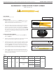
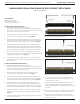
Figure A. Receiver Module.
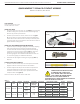
Figure B. ITA Module.
TOOLS REQUIRED
Phillips Head Screwdriver
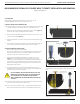
INSTALLATION INSTRUCTIONS
NOTE: The receiver strain relief plate or the ITA cover may need to
be removed prior to installing or removing an iCon module.
Please refer to the appropriate User’s Manual for instructions on
how to perform these steps.
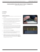
1. Place the module in the receiver or ITA until the upper and
lower module screws touch the mating holes in the frame. Install
modules such that Position 1 is located at the top of the ITA/
receiver frame.
2. Using a Phillips head screwdriver, tighten the top screw 1 to 2 full
revolutions, while pushing lightly against the face of the module.
3. Maintain this pressure while tightening the bottom screw 1 to 2
full revolutions.
4. Repeat this sequence until the module is seated. Torque the
screw to 1.5 in-lbs [0.16 Nm].
REMOVAL INSTRUCTIONS
1. To remove, loosen the top screw 1 to 2 full revolutions. Loosen
bottom screw 1 to 2 full revolutions.
2. Repeat this sequence until the module is separated from the
receiver or ITA.
NOTE: For optimum performance and system longevity, distribute
the contact load evenly throughout the module.