
Specifications


QUADRAPADDLE SIGNAL CONTACTS AND MODULES USER’S MANUAL: SECTION 2 VIRGINIA PANEL CORPORATION
1/26/10
2-1 For more information visit vpc.com
QUADRAPADDLE™ SIGNAL ITA CONTACT ASSEMBLY
PART # 610 138 109 / 610 138 112
OBSERVE PRECISION RATCHET ACTION
BY OPENING AND CLOSING TOOL
FULLY SEVERAL TIMES. NOTE THAT THE
TOOL CANNOT BE OPENED WITHOUT
COMPLETING A CYCLE. NEVER ATTEMPT TO
DISASSEMBLE TOOL. NEVER TIGHTEN OR LOOSEN STOP
NUTS ON THE BACK OF THE TOOL.
TOOLS REQUIRED
Crimp Tool, Part # 910 101 103
Locator, Part # 910 104 140
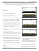
CRIMP TOOL SETUP
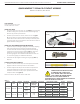
1. Set up the Crimp Tool, Part # 910 101 103 (Figure A), by loosening
the latch locking screw (counter-clockwise, until turning stops).
Remove any previously used locator.
2. Insert the open end of the Locator, Part # 910 104 140 (Figure
B), into the crimp tool locator retainer. Slide the retaining latch
toward the locator until the locator is securely locked into place.
The locator may have to be twisted to allow the latch to retain it.
Tighten the latch locking screw.
CRIMP TOOL ADJUSTMENT AND WIRE PREPARATION
1. Adjust the crimp tool setting by pulling the microcrimp adjusting
knob and turning it at the same time (clockwise increases,
counter-clockwise decreases setting) until the desired setting
is achieved on the microcrimp indicator (Table 1). Verify with
gauge pin. For more information about gauge pins, visit
vpc.com/gaugepins. See calibration instructions for Part # 910
101 102/103 for gauge pin verication instructions.
2. Determine the strip length according to wire gauge (Table 1).
Strip wire.
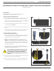
CONTACT SETUP AND CRIMPING
1. Insert the contact into the crimp tool and squeeze the handle
slightly to hold the contact in position for wire insertion.
2. Insert the stripped wire fully into the contact and squeeze the
crimp tool handle until a positive stop is reached. The tool
will release and return to a fully “open” position. Remove the
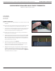
crimped contact wire (Figure C).
NOTE: This contact can also be used to solder wire.
Figure B. Locator, Part # 910 104 140.
Figure A. Crimp Tool, Part # 910 101 103.
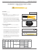
Table 1.
CONTACT CRIMP
TOOL
LOCATOR
DIE
STRIP LENGTH
(IN [MM])
INSULATION
DIAMETER MAX
(IN [MM])
WIRE GAUGE CRIMP SETTING (IN [MM]) PULLOUT
FORCE
(LBS [N])
EXTRACTION
TOOL
MAX MIN
610138109 910101103 910104140
0.200
[5.08]
0.040
[1.02]
22 0.030 [0.76] 0.026 [0.66] 10 [44.5]
910110111
24 0.026 [0.66] 0.022 [0.56] 8 [35.6]
0.250
[6.35]
2-24* 0.030 [0.76] 0.026 [0.66] 8 [35.6]
2-26* 0.029 [0.74] 0.026 [0.66] 4 [17.8]
610138112 910101103 910104140
0.200
[5.08]
0.040
[1.02]
26 0.032 [0.81] 0.031 [0.79] 4 [17.8]
28 0.027 [0.68] 0.026 [0.66] 2 [8.9]
30 0.023 [0.58] 0.022 [0.56] 1 [4.4]
* Pullout force is for individual wires
Figure C. Correctly crimped contact.
MICROCRIMP
ADJUSTING KNOB
MICROCRIMP
INDICATOR
RETAINING LATCH ASSEMBLY
AND LOCKING SCREW
LOCATOR
RETAINER