
Specifications


QUADRAPADDLE SIGNAL CONTACTS AND MODULES USER’S MANUAL: SECTION 4 VIRGINIA PANEL CORPORATION
1/26/10
4-2 For more information visit vpc.com
QUADRAPADDLE SIGNAL TWIN FEMALE RECEIVER CONTACT REPLACEMENT
PART # 610 138 100
TOOLS REQUIRED
Phillips Head Screwdriver
Flat Blade Screwdriver
Tweezers or Needlenose Pliers
CONTACT REMOVAL INSTRUCTIONS
1. Remove the module from the receiver frame.
NOTE: For more information concerning the process of removing the
module from the receiver frame, see module installation and removal
instructions in Section 5 of this User’s Manual.
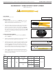
2. Use a Phillips head screwdriver to remove the two 2-56 screws
located at the top and bottom of the module (Figure A).
3. Insert the at blade screwdriver into the slot of the module and pry
the end of the module using a twisting motion until visible separation
is indicated. Repeat on the opposite end of the module (Figure A).
4. Grasp the module halves and apply force in opposite directions,
rocking the ends of the module while slightly pulling the top of the
module away from the mating bottom section. Be sure to open both
sides of the module simultaneously or contacts could be damaged.
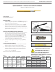
5. Use a pair of tweezers or a small pair of needlenose pliers to grasp
the contact. Pull the contact out of the module, taking care to avoid
damaging surrounding contacts (Figure B).
6. If an Adapter Pin, Part #610 138 117/118, needs to be removed, it
can be taken out at this point by turning the module over, allowing
the pin to fall out.
CONTACT INSTALLATION INSTRUCTIONS
1. Remove the module from the receiver frame.
NOTE: For more information concerning the process of removing the
module from the receiver frame, see module installation and removal
instructions in Section 5 of this User’s Manual.
2. Use a Phillips head screwdriver to remove the two 2-56 screws
located at the top and bottom of the module (Figure A).
3. Insert the at blade screwdriver into the slot of the module and pry
the end of the module using a twisting motion until visible separation
is indicated. Repeat on the opposite end of the module (Figure A).
4. Grasp the module halves and apply force in opposite directions,
rocking the ends of the module while slightly pulling the top of the
module away from the mating bottom section. Be sure to open both
sides of the module simultaneously or contacts could be damaged.
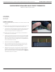
5. Align the square portion of the contact with the square opening in
the module. Insert the contact into the bottom half of the module
(Figure C).
6. Use your thumb or a at, non-marring surface to press the end of the
contact into the module.
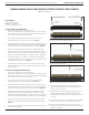
Figure A. The module is designed with a polarizing feature
to make sure the cap is properly aligned.
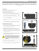
Figure B. Take care to avoid damaging contacts surround-
ing the one to be removed.
Figure C. Ensure the square portion of the contact is
aligned with the square opening in the module.
7. If an Adapter Pin, Part #610 138 117/118, needs to be
installed, place the pin into the protruding portion of the
contact, Part # 610 138 100.
8. Replace the module cap using both hands to push the
separated halves together. Replace and tighten the
module retaining screws to a maximum torque of 1.5 in-lbs
[0.16 Nm].
NOTE: The process shown here uses standard/90 series modules.
The same process is used for modules from other series.
NOTE: If you are using a hybrid module, you may need to
reference the User’s Manual for the other contact type for
extraction instructions.