
Specifications


QUADRAPADDLE SIGNAL CONTACTS AND MODULES USER’S MANUAL: SECTION 4 VIRGINIA PANEL CORPORATION
1/26/10
4-3 For more information visit vpc.com
QUADRAPADDLE SIGNAL ITA CONTACT INSTALLATION AND REMOVAL
PART # 610 138 109 / 610 138 112 / 610 138 115
TOOLS REQUIRED
QuadraPaddle ITA Extraction Tool, Part # 910 110 111
CONTACT INSTALLATION INSTRUCTIONS
1. Assemble the contact to the respective wire.
NOTE: For more information concerning the process of crimping
the contact, see contact assembly instructions in Section 2 of this
User’s Manual.
2. Insert the assembled contact into the back (wiring side) of the
assembled module (Figure A). The contact can only go into
one side. Once in place, pull the wire slightly to ensure that the
contact is seated.
REMOVAL INSTRUCTIONS
1. Remove the module from the ITA frame.
NOTE: For more information concerning the process of removing
the module from the ITA frame, see module installation and
removal instructions in Section 5 of this User’s Manual.
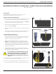
2. Place the QuadraPaddle ITA Extraction Tool, Part # 910 110 111
(Figure B), over the contact to be removed/replaced. Use care
to keep the tool perpendicular to the surface of the module as
to not bend the tool or the contact to be removed. Rotate the
tool slightly while pushing it into the counter bore on the mating
side of the module.
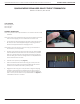
3. Once the extraction tool is seated properly and the tabs on the
retaining ring are compressed, push the plunger and the contact
will be pushed out of the rear of the module.
DO NOT DEPRESS THE PLUNGER ON THE BACK OF THE
EXTRACTION TOOL UNTIL THE TIP OF THE EXTRACTION
TOOL HAS BEEN FULLY SEATED INTO THE MODULE
AND COMPRESSED THE RETAINING RING TABS ON
THE CONTACT.
NOTE: The process shown here uses standard/90 series modules. The
same process is used for modules from other series.
NOTE: If you are using a hybrid module, you may need to reference
the User’s Manual for the other contact type for extraction
instructions.
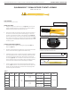
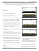
Figure A. Contacts inserted into the module.
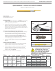
Figure B. Ensure that the tool is kept perpendicular to the
module face to avoid damage to the contact or tool.