
User's Manual

— 8 —
F35628 (10-04)
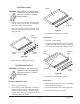
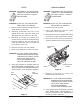
GAS BURNER
WARNING: DISCONNECT THE ELECTRICAL
POWER TO THE MACHINE AND
FOLLOW LOCKOUT / TAGOUT
PROCEDURES.
1. Remove the back panel.
2. Cut shipping tie from burner.
3. To remove the burner, reach through the
back of the unit and lift the burner up over
the guide screw then pull the burner out
through the back of the unit.
4. Replace the burner by inserting the burner
through the rear of the unit, engaging the
burner venturi onto the burner valve orifice
at the front of unit. From the front of the
unit, remove the control panel to check
that the venturi is properly fitted over the
orifice.
5. Reassemble the control and back panels
then check for proper operation.
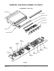
Figure H
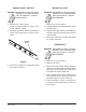
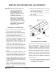
PILOT SOLENOID
WARNING: DISCONNECT THE ELECTRICAL
POWER TO THE MACHINE AND
FOLLOW LOCKOUT / TAGOUT
PROCEDURES.
WARNING: SHUT OFF THE GAS BEFORE
SERVICING THE GRIDDLE.
1. Remove the control panel.
2. Label and disconnect the two wires
connected to the solenoid.
3. Disconnect the input compression fitting
and the two output compression fittings.
4. Remove the two screws attaching solenoid
to single solenoid bracket and remove
solenoid.
Figure I
5. Reverse procedure to install the
replacement gas solenoid.
WARNING: ALL GAS JOINTS DISTURBED
DURING SERVICING MUST BE
CHECKED FOR LEAKS. CHECK
WITH SOAP AND WATER
SOLUTION (BUBBLES).
DO NOT USE AN OPEN FLAME.
6. Verify gas pressure as outlined under the
GAS PRESSURE ADJUSTMENT in
Service Procedures and Adjustments.
Check for proper operation.
Orifice
Guide
Screw
Burner
Output
Compression
Fittings
Input
Compression
Fitting
Remove
Screws