
Installation Sheet

Phone (800) 526.2588
Fax (800) 526.2585
44 Harbor Park Drive
Port Washington, NY 11050
1600 Distribution Ct
Lithia Springs, GA 30122
1750 Archibald Avenue
Ontario, CA 91760
3
INSTALLATION INSTRUCTION
PD-73129 / PD-73139
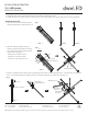
6. For Part 3, rotate the arm by 45 °with respect to the guiding hole as shown to reveal the mounting holes. Connect the wire connector with
Part 1. Secure the parts with the assembly screw(C), then rotate the arm to cover the holes as shown (Fig. 4) .
Note : All the six lamp arms can be adjustabed after installation. You can adjust the arms of the xture to desire position with the angle of
rotation not exceeding 30 degree.
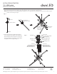
7. Remove the mounting screw (B) from the xture.
Choose number of rod suitable of your application.
Thread the xture wire through the rod, swivel and
canopy. Connect the canopy, swivel, rod and xture
body. Make sure all are tightened (Fig. 5).
45°
Fig . 4
Assembly
Screw
Male end
connector
Female end
connector
Part
3
Short end
Center of rotation
Center of rotation
Guiding hole
Fig . 5
Wire Connector
Mounting Screw
White Wire
Black Wire
Junction Box
Bare Copper Ground Wire
Junction Box Screw
Mounting Back Plate
Canopy
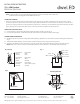
1×6" Rod
(RPL-ROD-IN06-AB)
(RPL-ROD-IN06-BN2-1)
(RPL-ROD-IN06-BK-01)
3×12" Rod
(RPL-ROD-IN12-AB)
(RPL-ROD-IN12-BN2-1)
(RPL-ROD-IN12-BK-01)