
User manual

1
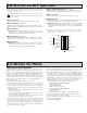
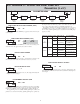
AIR PRESSURE STABILIZATION VENT
(57.15)
2.25
X
Z
Y
GENERAL DESCRIPTION
The Large Display Timer and Cycle Counter is a versatile display that
functions as an Elapsed Timer or Preset Timer, with full-featured user
programmability. The meter includes a built-in Cycle Counter, relay output and
serial communications capability. The 6 digit displays are available in either
2.25" or 4" high red LED digits with adjustable display intensity. The 2.25" high
models are readable up to 130 feet. The 4" high models are readable up to 180
feet. Both versions are constructed of a NEMA 4X/IP65 enclosure in light
weight aluminum.
The Timer has two signal inputs and eight input operating modes. These
modes provide level active or edge triggered start/stop operation. The Timer
features 18 selectable timer ranges to cover a wide variety of timing applications.
The built-in Cycle Counter can be linked to timer operation to count timing
cycles, or function as a totally independent counter, accepting count speeds up
to 500 Hz. The display can be toggled either manually or automatically between
the Timer and Counter values.
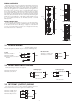
In addition to the Timer/Counter inputs, a programmable User Input is
provided to perform a variety of meter functions. DIP switches are used to
configure the inputs for current sinking (active low) or current sourcing (active
high) operation.
The Setpoint Output can be assigned to the Timer or Counter value, and
configured to suit a variety of control and alarm requirements. The meter also
includes RS232 or RS485 serial communications.
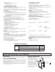
SAFETY SUMMARY
All safety regulations, local codes and instructions that appear in this and
corresponding literature, or on equipment, must be observed to ensure personal
safety and to prevent damage to either the instrument or equipment connected to
it. If equipment is used in a manner not specified by the manufacturer, the
protection provided by the equipment may be impaired.
Do not use this unit to directly command motors, valves, or other actuators
not equipped with safeguards. To do so can be potentially harmful to persons or
equipment in the event of a fault to the unit.
The protective conductor terminal is bonded to conductive
parts of the equipment for safety purposes and must be
connected to an external protective earthing system.
SPECIFICATIONS
1. DISPLAY: 2.25" (57 mm) or 4" (101 mm) intensity adjustable Red LED
2. POWER REQUIREMENTS:
AC POWER: 50 to 250 VAC 50/60 Hz, 26 VA
DC POWER: 21.6 to 250 VDC, 11 W
DC Out: +24 VDC @ 100 mA if input voltage is greater than 50 VAC/VDC
+24 VDC @ 50 mA if input voltage is less than 50 VDC
Isolation: 2300 V
RMS
for 1 min. to all inputs and outputs
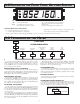
3. TIMER DISPLAY: 6-digits
Display Range: 0 to 999999
Overflow/Underflow Indication: Display flashes “”
Minimum Digit Resolution: 0.001 Sec.
Maximum Single Digit Resolution: 1 Hr.
Timing Accuracy: ±0.01%
4. CYCLE COUNTER DISPLAY: 5-digits, may be disabled if not used
Display Designator: “
” to the left side of the display
Display Range: 0 to 99999
Overflow/Underflow Indication: Display flashes “”
2.25" or 4" HIGH RED LED DIGITS
6-DIGIT BI-DIRECTIONAL TIMING CAPABILITY
5-DIGIT CYCLE COUNTING CAPABILITY
SELECTABLE TIMER RANGES AND OPERATING MODES
ELAPSED TIMER AND PRESET TIMER FUNCTIONALITY
SERIAL COMMUNICATIONS (RS232 or RS485)
PROGRAMMABLE USER INPUT
UNIVERSALLY POWERED
5 AMP FORM C RELAY OUTPUT
ALUMINUM NEMA 4X CASE CONSTRUCTION
MODEL LD - LARGE DISPLAY TIMER AND CYCLE COUNTER
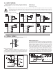
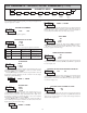
DIMENSIONS In inches (mm)
Bulletin No. LDT-E
Drawing No. LP0634
Released 10/09
Tel +1 (717) 767-6511
Fax +1 (717) 764-0839
www.redlion.net
CAUTION: Risk of Danger.
Read complete instructions prior to
installation and operation of the unit.
CAUTION: Risk of electric shock.
C
C
US LISTED
US LISTED
U
L
R
51EB
IND. CONT. EQ.
PART
NUMBER
X (Length) Y (Height) Z (Center)
LD2T06P0 16 (406.4) 4 (101.6) 12 (304.8)
LD4T06P0 26 (660.4) 7.875 (200) 22 (558.8)