
User manual


11
DATA BIT
ABBREVIATED PRINTING
PRINT OPTIONS
PARITY BIT
METER ADDRESS
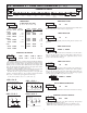
Module 5 is the programming module for the Serial Communications
Parameters. These parameters are used to match the serial settings of the meter
with those of the host computer or other serial device.
PAR
Data BitBaud Rate Parity Bit Print
Options
Meter
Address
Abbreviated
Printing
5.5 MODULE 5 - SERIAL COMMUNICATIONS PARAMETERS ()
PARAMETER MENU
BAUD RATE
Set the baud rate to match that of other serial communications equipment.
Normally, the baud rate is set to the highest value that all of the serial
communications equipment is capable of transmitting and receiving.
Select either 7- or 8-bit data word length. Set the word length to match the
other serial communications equipment on the serial link.
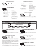
This parameter only appears when the Data Bit parameter is set to a 7-bit
data word length. Set the parity bit to match that of the other serial equipment
on the serial link. The meter ignores parity when receiving data and sets the
parity bit for outgoing data. If parity is set to
, an additional stop bit is used
to force the frame size to 10 bits.
Enter the serial node address. With a single unit, an address is not needed
and a value of zero can be used (RS232 applications). Otherwise, with multiple
bussed units, a unique address number must be assigned to each meter. The
node address applies specifically to RS485 applications.
This parameter determines the formatting of data transmitted from the meter
in response to a Transmit Value command or a Block Print Request. Select
for a full print transmission, consisting of the meter address, mnemonics, and
parameter data. Select for abbreviated print transmissions, consisting of the
parameter data only. This setting is applied to all the parameters selected in the
PRINT OPTIONS. (Note: If the meter address is 0, the address will not be sent
during a full transmission.)
to
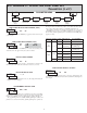
This parameter selects the meter values transmitted in response to a Print
Request. A print request is also referred to as a block print because more than
one parameter can be sent to a printer or computer as a block.
Selecting displays a sublist for choosing the meter parameters to appear
in the print block. All active parameters entered as in the sublist will be
transmitted during a block print. Parameters entered as will not be sent.
The “Print All” () option selects all meter values for transmitting
(), without having to individually select each parameter in the sublist.
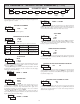
Note: Inactive parameters will not be sent regardless of the print option
setting. For example, the Cycle Counter and Cycle Counter Start values will
only be sent when the Cycle Counter is enabled. If disabled, these parameters
are inactive and will not be transmitted. Likewise, only the Setpoint parameters
that apply to the programmed Setpoint Output Action will be transmitted.
DISPLAY MNEMONIC
Timer
TMR
Cycle Counter
CNT
Timer Stop
Timer Start
TSP
TST
CST
SPT
Setpoint Time-out
Setpoint OFF
STO
SOF
DESCRIPTION
FACTORY
SETTING
Counter Start
Setpoint ON