
User manual


Command String Construction
The command string must be constructed in a specific sequence. The meter
does not respond with an error message to illegal commands. The following
procedure details construction of a command string:
1. The first 2 or 3 characters consist of the Node Address Specifier (N) followed
by a 1 or 2 character node address number. The node address number of the
meter is programmable. If the node address is 0, this command and the node
address itself may be omitted. This is the only command that may be used in
conjunction with other commands.
2. After the optional address specifier, the next character is the command
character.
3. The next character is the register ID. This identifies the register that the
command affects. The P command does not require a register ID character. It
prints all the active selections chosen in the Print Options menu parameter.
4. If constructing a value change command (writing data), the numeric data is
sent next.
5. All command strings must be terminated with the string termination
characters * or $. The meter does not begin processing the command string
until this character is received. See timing diagram figure for differences in
meter response time when using the * and $ terminating characters.
Command String Examples:
1. Node address = 17, Write 350 to the Setpoint On value
String: N17VF350$
2. Node address = 5, Read Timer value, response time of 50 msec min
String: N5TA*
3. Node address = 0, Reset Setpoint output
String: RF*
4. Node address = 31, Request a Block Print Output, response time of 2 msec min
String: N31P$
Transmitting Data to the Meter
Numeric data sent to the meter must be limited to Transmit Details listed in the
Register Identification Chart. Leading zeros are ignored. The meter ignores any
decimal point and conforms the number to the appropriate display format. (For
example: The Timer range is set for tenths of a second and 25 is written to the
Timer Start register. The value of the register is now 2.5 seconds. In this case,
write a value of 250 to equal 25.0 seconds).
Note: Since the meter does not issue a reply to value change commands, follow
with a transmit value command for readback verification.
12
Sending Serial Commands and Data
When sending commands to the meter, a string containing at least one
command character must be constructed. A command string consists of a
command character, a value identifier, numerical data (if writing data to the
meter) followed by a command terminator character, * or $.
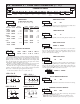
Command Chart
Register Identification Chart
ID
Value
Description
MNEMONIC Transmit Details (T and V)
A Timer TMR 6 digit, per Timer Range
B Cycle Counter CNT 5 digit
D
C
Timer Stop
Timer Start
TSP
TST
6 digit, per Timer Range
6 digit, per Timer Range
E Counter Start CST 5 digit
F
Setpoint ON
(Reset Output)
SPT
per Setpoint Assignment,
same as Timer or Counter
H
G
Setpoint
Time-out
Setpoint OFF
STO
SOF
6 digit, mm.ss.ss format
per Setpoint Assignment,
same as Timer or Counter
T, V, R
T, V, R
T, V
T, V
T, V
T, V, R
T, V
T, V
Receiving Data From The Meter
Data is transmitted from the meter in response to either a transmit command
(T), a block print request command (P) or a User Input print request. The
response from the meter is either a full field transmission or an abbreviated
transmission, depending on the selection chosen in Module 5.
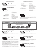
Full Field Transmission
* These characters only appear in the last line of a block print.
The first two characters transmitted are the meter address. If the address
assigned is 0, two spaces are substituted. A space follows the meter address field.
The next three characters are the register mnemonic, as shown in the Register
Identification Chart.
The numeric data is transmitted next. The numeric field (bytes 7 to 18) is 12
characters long. When a display overflow exists for a requested timer or cycle
counter value, an * (used as an overflow character) replaces a space in byte 7.
Byte 8 is always a space.
The remaining ten positions of this field consist of seven positions for the
requested value with decimal points positioned for the selected timer range. The
data within bytes 9 to 18 is right-aligned with leading spaces for any unfilled
positions.
The end of the response string is terminated with a <CR> and <LF>. After the
last line of a block print, an extra <SP>, <CR> and <LF> are added to provide
separation between the print blocks.
Abbreviated Transmission
* These characters only appear in the last line of a block print.
The abbreviated response suppresses the node address and register mnemonic,
leaving only the numeric part of the response.
Meter Response Examples:
1. Node address = 17, full field response, Cycle Counter = 875
17 CNT 875 <CR><LF>
2. Node address = 0, full field response, Setpoint On value = 250.5
SPT 250.5<CR><LF>
3. Node address = 0, abbreviated response, Setpoint On value= 250, last line of
block print
250<CR><LF><SP><CR><LF>
Byte Description
1, 2 2 byte Node Address field [00-99]
3 <SP> (Space)
4-6 3 byte Register Mnemonic field
7-18
19 <CR> (carriage return)
20 <LF> (line feed)
21 <SP>* (Space)
22 <CR>* (carriage return)
23 <LF>* (line feed)
Byte Description
1-12
12 byte data field, 9 bytes for number and three bytes for
decimal points
13 <CR> (carriage return)
14 <LF> (line feed)
15 <SP>* (Space)
16 <CR>* (carriage return)
17 <LF>* (line feed)
12 byte data field; 9 bytes for number and three bytes for decimal
points
Applicable
Commands
Initiates a block print output. Registers in the
print block are selected in Print Options.
Block Print Request
(read)
P
Reset a value or the output. Must be followed
by a register ID character
ResetR
Write to register of the meter. Must be
followed by a register ID character and
numeric data.
Value Change (write)V
Read a register from the meter. Must be
followed by a register ID character.
Transmit Value (read)T
Address a specific meter. Must be followed
by one or two digit node address. Not
required when node address = 0.
Node (meter)
Address Specifier
N
NotesDescriptionCommand