
User manual

2
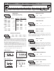
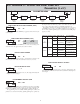
ORDERING INFORMATION
Maximum Count Rate:
All Count Sources except Input B: 10 Hz
Input B Count Source:
With Timer Input Filter ON: 10 Hz
With Timer Input Filter OFF: 500 Hz
5. TIMER SIGNAL INPUTS (INP A and INP B)
DIP switch selectable pull-up (7.8 K) or pull-down (3.9 K) resistors
determine active high or active low input logic.
Input A Trigger levels: V
IL
= 1.25 V max; V
IH
= 2.75 V min; V
MAX
= 28 VDC
Input B: Trigger levels: V
IL
= 1.0 V max; V
IH
= 2.4 V min; V
MAX
= 28 VDC
Inputs A and B:
Timer Input Pulse Width: 1 msec min.
Timer Start/Stop Response Time: 1 msec max.
Filter: Software filtering provided for relay or switch contact debounce.
Filter enabled or disabled through programming. If enabled, results in
50 msec start/stop response time for successive pulses applied to the
same input terminal.
6. RESET/USER INPUT Programmable Function Input:
DIP switch selectable pull-up (7.8 K) or pull-down (3.9 K) resistor
that determines active high or active low input logic.
Trigger levels: V
IL
= 1.0 V max; V
IH
= 2.4 V min; V
MAX
= 28 VDC
Response Time: 10 msec typ.; 50 msec debounce (activation and release)
7. COMMUNICATIONS:
RS485 SERIAL COMMUNICATIONS
Type: RS485 multi-point balanced interface (isolated)
Baud Rate: 300 to 38400
Data Format: 7/8 bits; odd, even, or no parity
Bus Address: 0 to 99; max 32 meters per line
RS232 SERIAL COMMUNICATIONS
Type: RS232 half duplex (isolated)
Baud Rate: 300 to 38400
Data Format: 7/8 bits; odd, even, or no parity
8. MEMORY: Nonvolatile E
2
PROM retains all programming parameters and
timer/count values when power is removed.
9. OUTPUT:
Relay: Form C contacts rated at 5 amps @ 120/240 VAC or 28 VDC (resistive
load), 1/8 H.P. @ 120 VAC (inductive load)
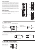
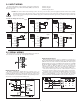
10. CONNECTIONS:
Internal removable terminal blocks are used for power and signal wiring.
Remove end plates with ¼" nut driver. For LD4 versions, all wiring is on right
side of unit. For LD2 versions, power and signal wiring connections are on
the right side and the relay and serial output options are on left side.
Wire Strip Length: 0.4" (10 mm)
Wire Gage: 24-12 AWG copper wire
Torque: 5.3 inch-lbs (0.6 N-m) max
Cable Diameter: Outside diameter must be 0.181" (4.6 mm) to 0.312" (7.9
mm) to maintain NEMA 4 rating of cord grips.
11. ENVIRONMENTAL CONDITIONS:
Operating temperature: 0 to 50 °C
Storage temperature: -40 to 70 °C
Operating and storage humidity: 0 to 85% max. RH (non-condensing)
Vibration According to IEC 68-2-6: Operational 5 to 150 Hz, in X, Y, Z
direction for 1.5 hours, 2 g’s (1g relay).
Shock According to IEC 68-2-27: Operational 30 g’s (10g relay), 11 msec in
3 directions.
Altitude: Up to 2,000 meters
12. CERTIFICATIONS AND COMPLIANCES:
SAFETY
UL Listed, File # E137808, UL508, CSA C22.2 No. 14-M95
LISTED by Und. Lab. Inc. to U.S. and Canadian safety standards
Type 4X Enclosure rating, UL50
IEC 61010-1, EN 61010-1: Safety requirements for electrical equipment for
measurement, control, and laboratory use, Part 1.
IP65 Enclosure rating, IEC 529
ELECTROMAGNETIC COMPATIBILITY
Emissions and Immunity to EN 61326: Electrical Equipment for Measurement,
Control and Laboratory use.
Notes:
1. Criterion A: Normal operation within specified limits.
13. CONSTRUCTION: Aluminum enclosure, and steel side panels with textured
black polyurethane paint for scratch and corrosion resistance protection. Meets
NEMA 4X/IP65 specifications. Installation Category II, Pollution Degree 2.
14. WEIGHT:
LD2T06P0 - 4.5 lbs (2.04 kg)
LD4T06P0 - 10.5 lbs (4.76 kg)
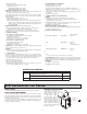
Class BEN 55011Emissions
Emissions:
0.5 cycle
Criterion A
3 V/rms
EN61000-4-11Voltage dip/interruptions
Criterion AEN 61000-4-6RF conducted interference
1 kV L-L,
Criterion AEN 61000-4-5Surge
1 kV signal
2 kV power
Criterion AEN 61000-4-4Fast transients (burst)
2 kV L&N-E power
10 V/m
Criterion AEN 61000-4-3Electromagnetic RF fields
8 kV air discharge
4 kV contact discharge
Criterion AEN 61000-4-2Electrostatic discharge
Immunity to Industrial Locations:
1.0 INSTALLING THE METER
INSTALLATION
The meter meets NEMA 4X/IP65 requirements when properly installed.
INSTALLATION ENVIRONMENT
The unit should be installed in a location that does not exceed the operating
temperature. Placing the unit near devices that generate excessive heat should be
avoided. The unit should only be cleaned with a soft cloth and neutral soap
product. Do NOT use solvents.
Continuous exposure to direct sunlight may accelerate the aging process of
the front overlay. Do not use tools of any kind (screwdrivers, pens, pencils, etc.)
to operate the keypad of the unit.
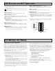
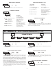
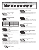
MOUNTING INSTRUCTIONS
This display is designed to be
wall mounted or suspended
from a ceiling truss or other
suitable structure capable
of supporting the LDT.
Caution should be exercised
when hanging the display to
provide for the safety of
personnel. If hanging the LDT,
run the suspension cables (or
chains) through the mounting
bracket holes. For wall mounting
use #10-32 size bolts.
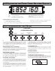
MOUNTING HOLE (.281")
MUST BE
CONNECTED TO
TERMINAL #3 (TBA)
MODEL NO. DESCRIPTION PART NUMBER
LD
2.25" High 6-Digit Red LED Timer/Cycle Counter w/ Relay Output &
RS232/RS485 Serial Communications
LD2T06P0
4" High 6-Digit Red LED Timer/Cycle Counter w/ Relay Output &
RS232/RS485 Serial Communications
LD4T06P0
LD Plug Panel Meter Plug for LD models (NOT included in LD Product UL File) LDPLUG00