
User manual

5
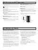
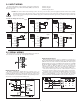
3.4 INPUT WIRING
The Large Display Timer is equipped with two signal inputs, A and B. These
inputs are wired using the six position terminal block (TBB) located inside the
unit on the right side.
Terminal 1: Input A
Terminal 3: Input B
Terminal 2: Input Common
CAUTION: DC common is NOT isolated from input common. In order to preserve the safety of the meter application, the DC common must be suitably
isolated from hazardous live earth referenced voltage; or input common must be at protective earth ground potential. If not, hazardous voltage may
be present at the User Input and Input Common terminals. Appropriate considerations must then be given to the potential of the input common with
respect to earth ground.
1
2
ON
3 4
* *
2.2 kΩ
1
INP A
RESET/USER
COMM
INP COMM
INP B
+EXC
4
6
5
3
2
TBB
2
1
ON
34
*
*
O.C.
NPN
1
INP A
RESET/USER
COMM
INP COMM
INP B
+EXC
4
6
5
3
2
TBB
1
2
3
ON
*
4
*
O.C.
PNP
TBB
+EXC
INP B
COMM
RESET/USER
6
5
3
4
INP COMM
2
INP A
1
1
2
34
ON
*
COMMON
+5 V
TBB
+EXC
INP B
COMM
RESET/USER
6
5
3
4
INP COMM
2
INP A
1
2
1
ON
* *
3 4
TBB
+EXC
INP B
COMM
RESET/USER
6
5
3
4
INP COMM
2
INP A
1
*
1
2
3
ON
*
4
RESET/USER
6
5
INP A
INP B
+EXC
3
4
2
1
TBB
COMM
INP COMM
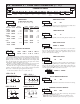
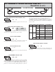
Two Wire Proximity, Current Source
Input A
Current Sourcing Output
Input A
Interfacing With TTL
Input A
Current Sinking Output
Input A
Switch or Isolated Transistor; Current Sink
Input A
Switch or Isolated Transistor; Current Source
Input A
*
Switch position is application dependent.
RS232 Communications
RS232 is intended to allow two devices to communicate over distances up to
50 feet. Data Terminal Equipment (DTE) transmits data on the Transmitted Data
(TXD) line and receives data on the Received Data (RXD) line. Data Computer
Equipment (DCE) receives data on the TXD line and transmits data on the RXD
line. The LD emulates a DTE. If the other device connected to the meter also
emulates a DTE, the TXD and RXD lines must be interchanged for
communications to take place. This is known as a null modem connection. Most
printers emulate a DCE device while most computers emulate a DTE device.
Some devices cannot accept more than two or three characters in succession
without a pause in between. In these cases, the meter employs a busy function.
As the meter begins to transmit data, the RXD line (RS232) is monitored to
determine if the receiving device is “busy”. The receiving device asserts that it
is busy by setting the RXD line to a space condition (logic 0). The meter then
suspends transmission until the RXD line is released by the receiving device.
RS485 Communications
The RS485 communication standard allows the connection of up to 32
devices on a single pair of wires, distances up to 4,000 ft. and data rates as high
as 10M baud (the LD is limited to 38.4k baud). The same pair of wires is used
to both transmit and receive data. RS485 is therefore always half-duplex, that is,
data cannot be received and transmitted simultaneously.
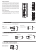
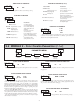
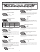
3.5 SERIAL WIRING
5
4
3
RS485 Terminal Block Connection Figure
1
2
3
RS232 Terminal Block Connection Figure
The serial connections are made via terminal block TBD located inside the
unit on the left side for the LD2 and on the right side for the LD4.