
User manual

6
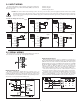
4.0 REVIEWING THE FRONT PANEL KEYS AND DISPLAY
PROGRAMMING MODE ENTRY (PAR KEY)
It is recommended all programming changes be made off line, or before
installation. The meter normally operates in the Display Mode. No parameters
can be programmed in this mode. The Programming Mode is entered by
pressing the PAR key. If it is not accessible, then it is locked by either a security
code or a hardware lock (See Module 3).
MODULE ENTRY (SEL & PAR KEYS)
The Programming Menu is organized into five modules. These modules group
together parameters that are related in function. The display will alternate between
and the present module. The SEL key is used to select the desired module.
The displayed module is entered by pressing the PAR key.
MODULE MENU (PAR KEY)
Each module has a separate module menu (which is shown at the start of each
module discussion). The PAR key is pressed to advance to a particular parameter
to be changed, without changing the programming of preceding parameters.
After completing a module, the display will return to . Programming
may continue by accessing additional modules.
SELECTION / VALUE ENTRY
For each parameter, the display alternates between the present parameter and
the selections/value for that parameter. The SEL and RST keys are used to
move through the selections/values for that parameter. Pressing the PAR key,
stores and activates the displayed selection/value. This also advances the meter
to the next parameter.
For numeric values, the value is displayed with one digit flashing (initially the
right most digit). Pressing the
RST key increments the digit by one or the user
can hold the RST key and the digit will automatically scroll. The SEL key
will select the next digit to the left. Pressing the
PAR key will enter the value and
move to the next parameter.
PROGRAMMING MODE EXIT (PAR KEY)
The Programming Mode is exited by pressing the PAR key with
displayed. This will commit any stored parameter changes to memory and return
the meter to the Display Mode. (If power loss occurs before returning to the
Display Mode, verify recent parameter changes.)
PROGRAMMING TIPS
It is recommended to start with Module 1 and proceed through each module in
sequence. When programming is complete, it is recommended to record the
parameter programming and lock out parameter programming with the user input
or programming security code.
FACTORY SETTINGS
Factory Settings may be completely restored in Module 3. This is useful when
encountering programming problems.
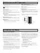
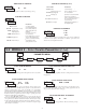
ALTERNATING SELECTION DISPLAY
In the explanation of the modules, the following dual display with arrows will
appear. This is used to illustrate the display alternating between the parameter
on top and the parameter’s Factory Setting on the bottom. In most cases,
selections and values for the parameter will be listed on the right.
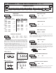
5.0 PROGRAMMING THE METER
Parameters
Output
Setpoint
Parameters
Timer Input
1SP
DISPLAY
MODE
Panel Key
Cycle Counter
Parameters
E41
Parameters
Display and Front
/0
PAR
SEL
PAR PAR PAR PAR
$OU
*/1
41U
4&S
PAR
Serial
Setup
Parameters
S
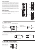
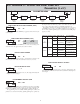
OVERVIEW
PROGRAMMING MENU
KEY DISPLAY MODE OPERATION PROGRAMMING MODE OPERATION
PAR Access Programming Mode Store selected parameter and index to next parameter
RST
SEL
Select display (Timer or Cycle Counter)
Advance through selection list/select digit position in
parameter value
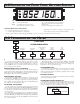
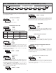
OPERATING MODE DISPLAY DESIGNATORS
“” - To the left of the display is the Cycle Counter value.
“ ” - Between digits 5 and 6 indicates the setpoint status.
“
” - Decimal point to the far right of the display can be programmed to flash
when the timer is running, to provide a “Timer Run” indicator.
If display scroll is enabled, the display will toggle automatically every four seconds between the Timer and Cycle Counter values.
Indicates Program Mode Alternating Display
Factory Settings are shown.
Parameter
Selection/Value
Reset value(s) per front panel reset setting Increment selected digit position of parameter value