
User manual

Timer Input
Operation
Timer Input
Filter
Timer Run
State At
Power-up
Timing
Direction
Timer Start
Value
Flash Timer
Run Indicator
Timer Reset
At Power-up
Timer
Range
PAR
User Input
Function
User Input
Assignment
Timer Stop
Value
7
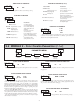
5.1 MODULE 1 - TIMER INPUT PARAMETERS ()
PARAMETER MENU
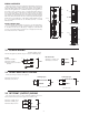
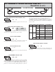
This parameter determines how the Timer Input Signals affect the Run/Stop
status of the Timer. Timing diagrams are shown below for level active and edge
triggered (1-input or 2-input) operation. For single input modes (Input A only),
Input B provides a level active Timer Inhibit function. In the Display Hold
mode, the timer display value remains held and only updates when a Timer
Start (Input A) or Timer Stop (Input B) edge occurs.
The timer reset () operating modes are identical to the other modes in the
diagrams, except the timer display value is reset at the Time Start edges.
The Timer can also be stopped at a Timer Stop Value or at Setpoint output
activation or deactivation. This type of Stop condition is cleared when a Timer
Reset occurs, or another start edge is applied on the timer input.
For Reset Modes (
), the timer is reset at Time Start edge.
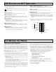
18 TIMER RANGE SELECTIONS
(= SEC; = MIN;= HR;= DAY)
TIMER RANGE
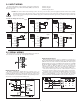
Level Active (Gated) Operation
INPUT A
INPUT B - Timer Inhibit (Level Active)
Time
Start
Time
Stop
Time
Start
Time
Stop
Edge Triggered Operation -1 Input
INPUT A
INPUT B - Timer Inhibit (Level Active)
Time
Start
Time
Stop
Time
Start
Time
Stop
,
,
TIMER INPUT OPERATION
0.01 HR
1 HR
0.1 HR
HOURS
0.1 MIN
0.01 MIN
MINUTES
1 MIN
0.01 SEC
0.001 SEC
1 SEC
0.1 SEC
MAXIMUM
DISPLAY
DISPLAY
RESOLUTION
RANGE
SELECTION
SECONDS
DAYS/HOURS/MINUTES
1 MIN
1 SEC
HOURS/MINUTES/SECONDS
0.1 MIN
0.01 MIN
HOURS/MINUTES
1 MIN
0.01 SEC
1 SEC
0.1 SEC
MAXIMUM
DISPLAY
DISPLAY
RESOLUTION
RANGE
SELECTION
MINUTES/SECONDS
TIMING DIRECTION
Bi-directional timing capability. Select the timing direction desired for the
application.
to
TIMER INPUT FILTER
Provides a 50 msec software debounce for the Timer Inputs (A and B). Select
when using relays or switch contacts as a signal source.
TIMER START VALUE
The Timer returns to this value whenever a Timer Reset occurs. The value is
entered in the same display format as the Timer Range selected. Non-zero
values are normally used for “timing down” applications, but they can also
provide an offset value when timing up.
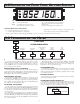
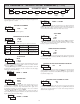
Edge Triggered Operation - 2 Input
INPUT A
INPUT B
Time
Start
Time
Start
Time
Stop
Time
Stop
Edge Triggered Operation - 2 Input,
with Display Hold
INPUT A
INPUT B
Time Stop,
Display Update
Time Start,
Display Update
Time Start,
Display Update
Display
Update
, ,
FLASH TIMER RUN INDICATOR
Select to have the Timer Run indicator flash when the timer is running.
TIMER STOP VALUE
The Timer stops when this value is reached regardless of the signal levels on
the timer inputs. Selecting displays a sub-menu where the Stop Value is
entered in the same display format as the Timer Range selected. This stop
condition is cleared when a Timer Reset occurs or another start edge is applied
on the timer input. Select if a Stop Value is not desired.
TIMER RUN STATE AT POWER-UP
Determines the Run/Stop state of the Timer at Power-up. This parameter
does not apply to Input Operation.
- Timer Stopped at power-up, regardless of prior Run/Stop state
- Timer assumes the Run/Stop state it was in prior to power-down
to