
User manual

8
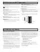
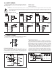
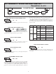
5.2 MODULE 2 - CYCLE COUNTER PARAMETERS ()
PAR
Cycle Counter
Count Source
Cycle Counter
Enable
Cycle Counter
Counting
Direction
Cycle Counter
Start Value
Cycle Counter
Reset At
Power-up
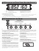
PARAMETER MENU
CYCLE COUNTER ENABLE
When set to , the remaining Cycle Counter parameters are not accessible.
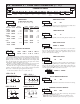
This parameter selects the source from which the Cycle Counter derives
counts. The Timer Reset () selection generates a count when either a
manual or automatic timer reset occurs (See Module 4 for programming
Automatic Reset). The Input B () selection generates a count each time
Input B is activated. This selection overrides the timer inhibit function of Input
B, when the timer is programmed for Level or Edge-1 operating mode (See
Module 1 for Timer Input Operating Modes).
The User Input () selection generates a count each time the User
Input is activated. When selected as the count source, the User Input can still be
set to perform a User Function described in Module 1. In this case, the Cycle
Counter will count the number of times the selected User Function occurred.
The Output ON/OFF selections generate a count when the Setpoint output
either activates or deactivates.
CYCLE COUNTER COUNT SOURCE
CYCLE COUNTER START VALUE
CYCLE COUNTER COUNTING DIRECTION
Bi-directional counting capability. Select the counting direction desired for
the application.
The Cycle Counter returns to this value whenever a Counter Reset occurs.
Non-zero values are normally used for “down counting” applications, but can
also provide an offset value when counting up.
to
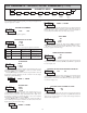
USER INPUT ASSIGNMENT
The User Input Assignment only applies if the cycle counter is enabled and
a selection of reset, display hold, hold and reset, inhibit, or print and reset is
selected in the User Input Function menu.
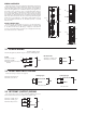
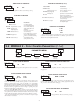
USER INPUT FUNCTION
USER INPUT FUNCTION (Cont’d)
MODEDISPLAY
No Function
DESCRIPTION
User Input disabled.
Program Mode Lock-out
Display Select
(Edge triggered)
Toggle display with each
activation.
Maintained Reset
Level active reset of the
selected value(s).
Display Hold
Hold and Reset
Edge triggered reset of the
selected value(s) after
storing the time or count.
See Programming Mode
Access chart (Module 3).
Freeze display for the selected
value(s) while allowing time or
counts to accumulate internally.
CYCLE COUNTER RESET AT POWER-UP
The Cycle Counter can be programmed to Reset at each meter power-up.
TIMER RESET AT POWER-UP
The Timer can be programmed to Reset at each meter power-up.
Serial transmit of the active
parameters selected in the Print
Options menu (Module 5).
Print Request
Edge triggered deactivation of
the Setpoint Output.
Same as Print Request followed
by a momentary reset of the
selected value(s).
Reset Output
Print and Reset
Inhibit timing or counting for the
selected value(s).
Increase intensity one level
for each activation.
DISPLAY DESCRIPTION
Inhibit
Display Intensity Level
(Edge Triggered)
MODE