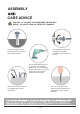
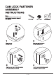
TOOLS REQUIRED Phillips Screwdriver (Not Included) Hammer (Not Included) 2 - Persons Recommended ASSEMBLY RATING EASY DIFFICULT The Assembly Rating is a 5-point system showing the level of effort needed to assemble a specific product.
/ 15
/ 15
ASSEMBLY CARE ADVICE FAILURE TO FOLLOW THE GUIDELINES BELOW MAY RESULT IN INJURY AND/OR PROPERTY DAMAGE. Turn clockwise to tighten and only tighten when step is completed or when instructed to do so. Position each part correctly and insert screws or bolts into their respective holes. Use the appropriate hand tools or power tools for assembly. Select steps, such as tightening screws and/or bolts, may require hand tools to avoid causing damage during assembly.
/ 15
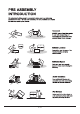
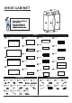
SHOE CABINET E G N F B J J H I PARTS A 1PC E 1PC J 2PCS P 1PC K 4PCS F 1PC Q 1PC B 1PC L 1PC G 1PC R 1PC C 1PC M 1PC H 2PCS S 1PC N 1PC D 1PC I 2PCS T 1PC O 1PC ACCESSORIES HARDWARE 1 18PCS 2 18PCS 3 14PCS 4 4PCS 1.25" 6 2PCS 7 16PCS 8 1PC 0.59" 11 2PCS 0.39" 9 2PCS 5 22PCS 10 2PCS A2 1PC A3 4PCS A4 1PC A7 1PC A8 1SET 1" 1.97" A5 1PC A6 1PC 0.71" 0.67" 12 2SETS 13 6PCS A1 1PC 14 6PCS 0.
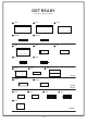
GET READY Please group boards as below.
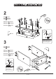
1 9 Hardware 1 Hardware 3 Hardware 8 Hardware 9 Hardware 10 Hardware 11 Hardware 12 1 9 x18PCS x2PCS x1PC x2PCS x2PCS x2PCS x2SETS front 8 1 1 A 1 1 1 1 1 1 1 1 1 1 E 1 H 12 X2 11 10 3 J A5 X2 OPTIONAL 12 Apply a dab of glue into dowel holes of panels before inserting dowels (#3).
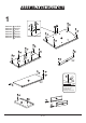
2 A4 Part D x1PC Part H x2PCS Part I x2PCS 5 5 5 5 5 5 5 5 5 Hardware 2 x4PCS Hardware 5 x10PCS 5 Accessory A4 x1PC D Top I Front H 2 2 2 1 2 I H 2 Please refer to page 5 for detailed instructions on how to fasten cam locks (#2) to cam bolts (#1).
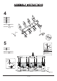
4 Part A Part F Part G Part L Part M x1PC x1PC x1PC x1PC x1PC G L A M Hardware 5 x8PCS 5 F Accessory A4 x1PC 5 5 5 5 Front 5 Top 5 A4 5 5 3 A5 Part E x1PC Part R x1PC OPTIONAL Apply a dab of glue into dowel holes of panels before inserting dowels (#3).
6 Part S x1PC Top Hardware 2 x4PCS A Front 2 2 2 2 1 S C B 2 7 Part K x4PCS Top Hardware 7 x16PCS Front K K 7 K Insert shelf pins (#7) to the holes of the desired shelf height.
8 Top Part J x2PCS Front J J Insert the side with fixed door pin (#12) first before inserting spring assisted door pin (#12).
10 Hardware 6 x2PCS 6 Top N Front Fully extend drawer rails then align the rails smallest hole to the drawer slide panels holes. Secure with bolts (#6). X2 11 Hardware 13 x6PCS Hardware 14 x6PCS Top 13 14 Front S Insert fixative plates (#13) through the thin lined gaps between back and side panels, then secure by using screws (#14).
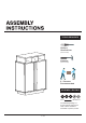
12 A7 Accessory A6 x1PC Accessory A7 x1PC Accessory A8 x1SET A6 Top A8 Front S For safety, please secure unit onto wall by using wall mounted straps provided. Refer to page 15 on wall mounting guide. 13 ASSEMBLY COMPLETED Please ensure the furniture rests on an even and flat surface. If the produst wobbles or feels loose,double-check all bolts and/or screws are properly tightened and secured.
/ 15