1 A HE URE FREE SD GG SRE GHD GR GHEE GD GHD TIER BEER GHD GED FREE GHD RUED TIER BEER GE RED FREE GOH GED CRED GR GORE RUD FREE GHB SERB GREG GRD FREE GRE GRR GIB GHD SRE HB CRIB GRR RRB GE SHED SR GIR GIRD GHB GR GE CRB SD GND GHD RE ERG SAFETY RULES 1. To reduce the risk of electric shock, insure electricity has been turned off at the circuit breaker or fuse box before beginning. 2. All wiring must be in accordance with the National Electrical Code and local electrical codes.
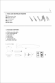
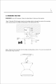
2 2. TOOLS AND MATERIALS REQUIRED ® Philips screw driver ® Blade screw driver ® 11 mm wrench Step ladder ® Wire cutters 3. PACKAGE CONTENTS a. Ceiling mounting plate b. Fan motor assembly c. Fan blades (2) d. Light plate e. Glass shade f. Accessories bag g.
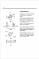
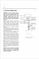
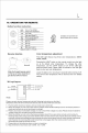
3 AD SRG GD GR GD GRE SR GH GD GREG ED GHEE RD GH RE SEER GH GD FREE BRD FREE RED MERE GH CRED FREE GORE GE CRED FREE GONE RED GEE GHB GREG RUED GRE GHB CRED GREG GIB SR RD GRE GRD HME GRR RRB GR SHED GORE GR GHB CRB REND GME CID SR GIR GHD doa Outlet box Fig. 2 ANGLED CEILING MAXIMUM ID ANGLE A Provide strong Recessed outfield box se Ceiling mounting plate Fig. 3 Outlet box Fig. 4 4.
HANGING THE FAN REMEMBER to turn off the power. Follow the steps below to hang your fan properly. Step 1. Pass the 120 Volt supply wires from the ceiling outlet box through the center of the mounting plate. Securely attach the ceiling mounting plate to the ceiling junction box. SN EPAULET Listed ' outlet box i Mounting | plate Dab amen 1 <= Screw Step 2. Hook the motor assembly onto the ceiling mounting plate as shown. You can now proceed with the electrical wiring of your fan.
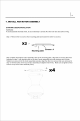
5 eG RE GND GR WE GND DE GH GHD THD GER DG A 6. ELECTRIC CONNECTIONS WARNING: To avoid possible electrical shock, be sure you have turned off the power at the main circuit panel. Follow the steps below to connect the fan to your household wiring. Use the wire Outlet box connecting nuts provided with your fan. White (neutral) Secure the connectors with electrical tape. Black (hot) Make sure there is no loose wire strand or Green or bare connection. Black ("AC IN copper (ground) White ("AC IN N") STEP 1.
6 7. INSTALL FAN MOTOR ASSEMBLY STANDARD CEILING INSTALLATION WARNING: To avoid possible electrical shock, be sure electricity is turned off at the main fuse box before wiring. Step 1. Remove the two screws from mounting plate and loosen the other two screws. Ra + omy Screws x 4 Mounting plate Step 2. Raise and hold the motor assembly close to the mounting plate. Align the two screws that were loosened in step 1) with keyhole slots on the top of motor assembly and twist clockwise until it locks.
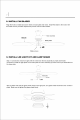
7 8. INSTALL FAN BLADES Align the holes on blade and screw holes on base plate and motor. Install the blade to the motor with the blade screws provided. Repeat this process with the other blades. Blade screws 9. INSTALL LED LIGHT KIT AND LAMP SHADE Step 1. Connect the wires from light with the wires from the fan assembly by male and female connectors. Install the light plate on the base plate of motor assembly by three screws per-assembled on the base plate. sow ui KINK Step 2 .
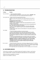
8 10. OPERATION FOR REMOTE Button function instruction LIGHT Tum an / Turn off light re ON/OFF change color temperature M&S stop Tum off fan (oor 1 High ey Installation of transmitter wall or MED Medium speed (Speed 2) Mount holder with two screws. Low Low speed (Speed 1) G0 1H Timer 1h 2H Timer 2h 4H Timer 4h nN. Rl Mute sound control Battery for emitter: 2 x 1.5V AAA id Reverse function Color temperature adjustment ERT Co ) This LED Light Source has three color temperatures: 3000K, 4000K, 6000K.
9 11. TROUBLESHOOTING Problem Fan will not start. Fan sounds noisy. Fan wobble. Fan not control. Solution 1. Check circuit fuses or breakers 2. Check all electrical connections to insure proper contact. CAUTION: Make sure the main power is OFF when checking any electrical connection. 1. Make sure all motor housing screws are snug. 2. Make sure the screws that attach the fan blade brackets to the motor are tight. 3.