
Instruction manual


EN
Operation
27
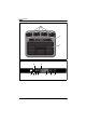
5.2 Control panel
The following control and display elements are available on the control panel
for operating the system:
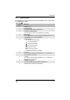
No. in fig. 2,
page 3
Meaning
1 ON/OFF button
2 Fault LED (red):
The LED indicates system malfunctions.
3 Compressor LED (yellow):
The LED lights up when the compressor is operating.
4 Mode button:
Use the Mode button to switch between operating modes 1, 2, 3
or Automatic and the Timer function.
5Digital display for:
–the selected operating mode
for operating mode 1
for operating mode 2
for operating mode 3
A for automatic mode
000 for the timer function
–Selected temperature in °C (target)
6 + button:
The + button increases the temperature by 1 °C or the timer
running time by 10 minutes.
7 – button:
The – button decreases the temperature by 1 °C or the timer
running time by 10 minutes.
8 POWER LED (green):
The LED indicates that the system is switched on.
9 Infrared receiver (for the remote control)
BA_CA850S_SP950.book Seite 27 Mittwoch, 2. Mai 2012 5:05 17