Diaphragm Diaphragm Pumps Pumps 1150 1150 Piston Piston Pumps Pumps EP2105 EP2105 EP2205 EP2205 EP2300 EP2300 EP2300se EP2300se EP2400 EP2400 EP2510 EP2510 GP2605 GP2605 GP2905 GP2905 HVLP HVLP CS5100 CS5100 CS8100 CS8100 CS9100 CS9100 Maxum Maxum IIII Gun Gun
EP2300 Piston Pump Owner's Manual Model Numbers: 0294006 Cart Mount 0294036 Low Boy SprayTECH 1770 Fernbrook Lane Minneapolis, MN 55447 1297 © 1997 Wagner Spray Tech. All rights reserved. Form No.
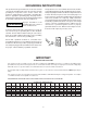
GROUNDING INSTRUCTIONS This product must be grounded. In the event of an electrical short circuit, grounding reduces the risk of electric shock by providing an escape wire for the electric current. This product is equipped with a cord having a grounding wire with an appropriate grounding plug. The plug must be plugged into an outlet that is properly installed and grounded in accordance with all local codes and ordinances.
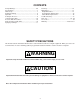
CONTENTS Clean-up.......................................................................12 Maintenance.................................................................13 Daily Maintenance......................................................13 Repacking the Fluid Section.......................................14 Motor Brush Replacement..........................................16 Trouble Shooting...........................................................17 Parts List...........................................
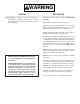
WARNING HAZARD PREVENTION Injection Injury - A high pressure stream of paint produced by this equipment can pierce the skin and underlying tissues, leading to serious injury and possible amputation. • Maximum operating range of the gun - 3000 PSI fluid pressure. • NEVER aim the gun at any part of the body. • NEVER allow any part of the body to come in contact with the fluid stream. DO NOT come in contact with a fluid stream created by a leak in the fluid hose. • NEVER put hand in front of the gun.
WARNING PREVENTION HAZARD Explosion or fire - Solvent and paint fumes can explode or ignite causing property damage and or severe injury. • Exhaust and fresh air introduction must be provided to keep the air within the spray area free from accumulation of flammable vapors. • Avoid all ignition sources such as static electricity sparks, open flames such as pilot lights, hot objects such as cigarettes, and sparks from connecting and disconnecting power cords and working light switches.
WARNING HAZARD PREVENTION Explosion hazard incompatible materials - May cause property damage or severe injury. • Halogenated hydrocarbon solvents such as methylene chloride and 1,1,1 - Trichlorethane are not compatible with aluminum and may cause an explosion. If unsure of a material’s compatibility with aluminum, contact your coating's supplier. • Some spray guns and accessories cannot be used with halogenated hydrocarbon solvents.
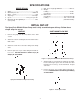
SPECIFICATIONS MODEL EP2300 1. 2. 3. 4. 5. 6. 7. Max. Hose Length @ 2000 PSI-----------------100 feet 8. Weight: LowBoy--------------------------------------------------63 lbs. Cart Mount--------------------------------------------- 64 lbs. 9.
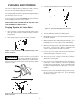
PURGING AND PRIMING 4. Set Prime/Spray Ball Valve to the Prime position. This unit is shipped with test fluid in the fluid section to prevent corrosion during shipment and storage. For spraying with solvent-based paint, thorough flushing of this material is not necessary. If you are going to spray with LATEX paint, this fluid must be thoroughly cleaned out of the system. KEEP SPRAY GUN LOCKED AND IN THE OFF POSITON DURING ALL THESE STEPS. Purging System for Latex Paint Figure 5.
For a new unit, follow purging and priming steps above. For units already in service, also purge water or solvent from the system as described above, depending on the type of paint being used. Purging System for Solvent-Based Paint If you are going to spray solvent-based paint, all you need to do is purge the fluid. Thorough cleaning is not necessary as it is with latex paint. After pump is primed and ready to spray, it may also be necessary to purge the hoses of water or solvent.
Using the Spray Gun Prime the Sprayer with Paint 1. Turn the prime/spray ball valve to prime. NOTE: FOLLOW THE INSTRUCTIONS THAT CAME WITH YOUR GUN. 2. Put the suction tube into the paint container. 3. Turn the pressure control knob counterclockwise as far as possible to the lowest pressure setting. 4. Start motor. Slowly increase pressure by turning the pressure control knob clockwise until pump begins to function.
Spraying Technique Light Coat Heavy Coat You can learn to spray paint as easily as you can learn to paint with a brush or roller. You can get a professional looking job in a safe manner by following the spray painting tips below. Light Coat Work 1. Heed all WARNINGS and CAUTIONS that are listed on pages 3 thru 6 at the front of this manual. Take time out now to reread them. 2. Avoid sharp bending and kinking of the paint hose.
7. The spray gun should be triggered (turned off and on) on each stroke. This will save paint and avoid paint buildup at the end of the stroke. However, do not trigger during the middle of a stroke. This will result in an uneven spray and splotchy work. See Figure 10 for proper triggering on a left-to-right stroke. Reverse for a right-to-left stroke. CLEAN-UP The pump, hose and gun should be cleaned thoroughly after daily use.
MAINTENANCE Routine operator maintenance on this unit is minimal. Only three daily procedures are required: (1) lubricating the upper packings, (2) cleaning the high pressure filter screen, and (3) cleaning the intake screen. Filter Housing Filter Support Daily Maintenance O-Ring 1. Squirt upper packing lubricant into slots in upper pump housing. Do not over-lubricate, as this will result in oil dripping into the paint. Oil approximately every four hours of operation. Filter Element Figure 12.
Repacking the Fluid Section ALWAYS follow the Pressure Relief Procedure (page 10) before starting any troubleshooting, servicing, or cleaning. A small amount of paint by-passing the piston and coming out of the slots in the upper piston housing is normal, but if it becomes excessive, or if paint pressure drops, the piston packings need to be replaced. WARNING Refer to Figure 14 (left). 1. Loosen and remove siphon tube assembly by turning counterclockwise. 1 *2 *4 2. Remove front cover. *3 3.
Repacking Fluid Section 34. Soak new leather packings in linseed oil for 5 minutes. Do not oversoak. Continued from Page 14 35. Insert wave spring (9) and lower male adapter (11) into cylinder. Remove leather packings from oil. Install leather packings (13) alternatively with UHMWPE packings (12). Insert lower female adapter (14). (Refer to Figure 14, Page 14) 16. Remove lower O-Ring (27) from inlet valve holder. 17. Place cylinder (8) in vise (on wrench flats) and tighten. CAUTION 36.
WARNING NEVER OPERATE PUMP WITHOUT FRONT COVER IN PLACE. Motor Brush Replacement Brushes should be inspected periodically to insure uninterrupted service. Their life depends on speed as well as load. Brush Cap If one of the brushes measures less than 1/4'' or is worn roughly or chipped, replace both motor brushes. It is also recommended that brushes be checked when packings are replaced. 1. Disconnect power cord from electrical supply. Motor Brush 2.
TROUBLESHOOTING PROBLEM CAUSE REMEDY Unit will not run Blown panel fuse or tripped breaker Unit not plugged in Pressure control knob set too low Faulty or loose wiring Check and replace/reset Worn motor brushes Clogged Tip or Filters Faulty On/Off switch fuse Unit will not prime Dried out piston packings Remove siphon tube and feel lower ball check to be sure it is free to move off its seat. Place full cup of paint thinner over end of fluid section and turn on pump. Remove and clean.
TROUBLESHOOTING CONTINUED PROBLEM CAUSE REMEDY Poor spray pattern Tip too large Pressure adjustment wrong Insufficient fluid delivery Fluid too viscous Change to smaller tip Adjust pressure control knob Clean all strainers and filters Add solvent according to manufacturer's recommendations Unit lacks power Pressure adjustment low Improper voltage supply Increase pressure Reconnect input voltage for 115 AC Blow Fuses at Pump Excessive pressure Circuit Breaker Overtightened packings gear box, linkag
26 20 25 24 3 4 2 23 5 1 22 15 14 9 10 21 7 8 6 6 20 19 18 13 12 9 10 17 11 16 2 Figure 16- EP2300 Final Assembly EP2300 FINAL ASSEMBLY - FIGURE 16 ITEM PART NO.
24 18 23 22 8 9 5 21 6 1 10 20 11 12 17 7 19 18 6 16 2 3 13 15 14 4 3 2 4 5 Figure 17- Low Boy Final Assembly EP2300 LOW BOY FINAL ASSEMBLY - FIGURE 17 ITEM PART NO. 1 -------- 2 3 4 5 6 7 8 51357 52183 13549 05045 51055 02518 0294220 0294228 9 10 11 12 9885559 0294424 9885547 02208 DESCRIPTION QTY. ITEM LowBoy Cart Assembly 1 (See Figure 19) Washer, Lock 4 Bolt, Hex. Hex.
1 2 3 4 5 6 7 8 Figure 18 - Cart Assembly CART ASSEMBLY - FIGURE 18 ITEM PART NO. DESCRIPTION 1 2 3 4 5 0279324 9802518 0288661 0294558 0270318 Handle Bolt Knob Frame, Cart Wheel ITEM PART NO. DESCRIPTION QTY. 1 2 2 1 6 7 8 21 9890104 54458 13538 0294534 Cap, Axle Screw Bumper Spacer, Wheel (NOT SHOWN) QTY.
1 2 3 4 5 4 7 6 8 Figure 19- LowBoy Cart Assembly LOWBOY CART ASSEMBLY - FIGURE 19 ITEM PART NO. DESCRIPTION 1 2 3 4 0294445 9802518 0288661 0294534 Handle, Cart Bolt, Carriage Knob, Handle Spacer, Wheel QTY. ITEM PART NO. DESCRIPTION 5 6 7 8 1 2 2 4 22 0270318 9890104 0294579 0270343 Wheel Cap, Hub Cart Foot, Rubber QTY.
1 8 2 7 3 4 6 5 18 19 20 17 21 10 9 14 13 16 11 15 12 Figure 20 - Pressure Control Assembly PRESSURE CONTROL ASSEMBLY - FIGURE 20 Item 1 2 3 4 5 6 7 8 9 10 11 Part No. Description 0294837 0295426 02585 0089986 0294349 0275703 9850630 52671 0294428 02491 9850629 02712 0294359 Pressure Increase Label Knob Toggle Boot On/Off plate Housing Strain relief Strain relief (CSA) Ring terminal Cord set Cord Set (CSA) Strain relief Spring Plunger Qty. Item 1 1 1 1 1 1 1 1 1 1 1 1 23 Part No.
0294133 FLUID SECTION ASSEMBLY FIGURE 21 NOTE: #1 Torque 25 FT. LBS.
TRANSDUCER ASSEMBLY FIGURE 22 1 ITEM PART NO. DESCRIPTION 2 3 8 4 5 6 1 2 3 4 5 6 50431 50504 02216 02232 50512 50482 02305* 7 50423 8 02283 QTY Retainer ring O-ring Transducer body Piston Back-up ring O-ring - Standard material O-Ring - Lacquer based material Retainer ring 1 1 1 1 1 1 1 1 Transducer Packing Kit Includes Items 1, 2, and 4 through 7.
EP2300 MOTOR ASSEMBLY - FIGURE 24 3 2 ITEM 1 2 3 4 5 6 7 8 9 10 1 4 PART NO. DESCRIPTION 01678 01694 01686 01783 19498 50148 50865 01791 50962 *01961 Brush Holder Motor Brush Brush Cap Stud Stator Assy. #10 Lockwasher 10-32 Nut Belleville Washer Bearing-Commutator End Armature w/Bearings 5 * Includes #50962 Bearing 6 6 7 7 8 9 8 10 9 NOTE: Washers must be stacked as shown. 6 7 EP2300 Motor Assembly - Figure 24 26 QTY.
6 4 3 9 8 7 5 10 2 1 7 6 15 39 40 14 11 13 16 38 37 18 17 36 35 19 24 34 33 32 22 25 31 30 27 21 20 23 26 12 29 28 EP2300 Drive Assembly - Figure 25 EP2300 DRIVE ASSEMBLY - FIGURE 25 ITEM PART NO.
1 2 3 4 5 6 7 8 9 ∆ ∆ 1 2 Figure 26 - Dump Valve Assembly 0294220 DUMP VALVE ASSEMBLY - FIGURE 26 ITEM PART NO. DESCRIPTION 1 2 0294194 14069 14068 3 4 9894245 14072 Filter Body Assembly Filter Sieve (50 Mesh) Filter Sieve (100 Mesh) (OPTIONAL) Support, Filter O-Ring QTY. ITEM 1 1 5 6 7 8 9 1 1 PART NO.
1 2 3 4 5 6 {∆∆ 1 See Note Page 28 2 Figure 27 - Dump Valve Assembly DUMP VALVE ASSEMBLY - FIGURE 27 Item Part No. Description Qty. 1 2 3 0294502 0294966 0294499 Housing, Dump Valve Repair Kit Seal, Dump Valve 1 1 1 Item 4 5 6 Part No. 0294516 9841502 0294214 Description Seat, Valve Ball, 10mm Dump Valve Cartridge Qty. 1 1 1 1 2 3 4 5 6 Convex 7 Concave Convex 8 Figure 28 - Dump Valve Cartridle DUMP VALVE CARTRIDGE - FIGURE 28 Item 1 2 3 4 Part No.
ACCESSORIES GUN FILTERS Part Number Description 0153—— 0153003 0291004 0291003 0291002 0291000 0093896 0088154 0153043 0153042 0152001 0152308 0152307 0152309 0152310 0152235 0152236 0152237 0152238 0152700 0149017 0093930 0152909 0152900 0502007 0502008 0502009 0270214 0502012 Part No.
Limited Warranty Commercial Airless Spray Equipment Two Year Warranty Spray Tech, a division of Wagner Spray Tech Corporation ("Spray Tech"), warrants this product against defects in material and workmanship for a period of two years following the date of purchase by the original purchaser.