Foreword Foreword Thank you for purchasing the Waldorf Rocket synthesizer. You now own a very compact analog synthesizer with an extraordinary look and astonishing sound. We know that already and you will know soon too. You have our word! effort to ensure the information herein is accurate and that the manual contains no contradictory information. Waldorf Music extends no liabilities in regard to this manual other than those required by local law.
Foreword We would like to thank The Rocket Development Team Hardware: Oliver Rockstedt, Frank Schneider Software: Oliver Rockstedt, Stefan Stenzel, Wolfram Franke Design: Axel Hartmann Manual/ Layout: Holger Steinbrink Revision: 1.0, February 2013 w Karsten Dubsch, Willie Eckl, Joachim Flor, Michael von Garnier, Erik Heirman, Frédéric Meslin, Kurt "Lu" Wangard, 吴海彬, and anyone we have forgotten. Please visit our website http://rocket.waldorfmusic.de.
Content Content Setup and Connection ........................................................ 11 Foreword ................................................................................ 2 Package Contents .......................................................... 11 What to read? .................................................................. 2 Connections .................................................................. 11 Hint ....................................................................
Content Sound Synthesis Basics ..................................................... 25 Glossary ......................................................................... 36 Oscillators Introduction ................................................. 25 Declaration of Conformity ............................................. 41 Filter Introduction .......................................................... 29 FCC Information (U.S.A.) ............................................... 43 Appendix ...........
Control Features and Connections Control Features and Connections Front Panel Rocket User´s Manual 6 a Headphone Volume Dial b Oscillator Controls c Filter Controls d Launch Button/ MIDI Input Indicator e LFO/ Arpeggiator Controls f Envelope Controls
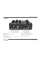
Control Features and Connections Connections A MIDI Out Jack E Audio Line Output (Mono Jack) B MIDI Channel Selection Button 6 VCF Audio Line Input (Mono Jack) C MIDI In Jack 7 Stereo Headphone Jack D USB Port for power supply and connection to a suited computer 7 Rocket User´s Manual
Introduction Introduction About this Manual Highlighted Control Features and Parameters This manual was written to help you become familiar with the Rocket synthesizer. It will also aid experienced users with routine tasks. All of the Rocket´s buttons, controls and parameters are highlighted in bold letters throughout the manual. Example: To avoid confusion, the terminology in this manual is based on the Rocket parameter names.
Introduction General Safety Guidelines Power Supply m • If not connected to a computer via USB, please use only the supplied USB power supply. • Unplug the device when you are not using it for longer periods. • Always pull the plug when unplugging the device, never the cable. Please read the following safety tips carefully! They include several precautions you should always observe when dealing with electronic equipment.
Introduction Maintenance • Do not open the device or remove the cover. Refer all service and repair tasks to qualified personnel. There are no user serviceable parts inside the chassis. • Use only a dry, soft cloth or brush to clean the device. Never use alcohol, cleaning solutions or similar chemicals. They will damage the surface of the chassis. Proper Use This device is designed exclusively to produce lowfrequency audio signals for the purpose of generating sound.
Setup and Connection Setup and Connection Connections Package Contents • the Waldorf Rocket Synthesizer • an external USB power supply as well as an USB cable In order to get started with your Rocket you will need an AC power outlet or a suitable computer with an USB port. For the connection of the audio output you will need either a mixing console or an audio interface. You can also use a suitable headphone. Last but not least you will mostl likely need a MIDI master keyboard.
Setup and Connection w 4. If you want to use a computer with a MIDI interface, connect your interface´s MIDI Out jack to the Rocket´s MIDI In jack 5. 5. Optionally you can connect the Rockets´s USB port 4 with a USB cable to your computer. After that the Rocket is automatically available as a MIDI unit and will also receive power via the USB connection. w 6. Without a computer, you need to connect the USB power supply that came with the Rocket to the USB port 4 of the Rocket.
w The USB Connection Using a USB cable you can connect the Rocket to your computer observing the following system requirements: • Windows PC: Windows XP or newer is recommended, a USB port • Linux PC, a USB port • Apple: Intel Mac with Mac OS X 10.5 or newer, a USB port Keep also in mind that we offer new firmware updates from time to time. Please read also the chapter "Updating the Firmware".
Basic Operation Basic Operation Editing Parameters Switching on/ off In order to edit a sound, you must access the appropriate parameters. In spite of the Rocket’s compactness it uses a sophisticated user interface allowing fast editing of any parameter. The Rocket is ready-to-operate after the connection to the USB power supply or via USB cable to a suitable computer. Turning a dial clockwise increases the corresponding value; turning it counterclockwise decreases it.
Sound Parameters Sound Parameters • Overview of Functions The Waldorf Rocket consists of numerous sound-shaping components w Modulators: The Modulators are designed to manipulate or modulate the sound generating components to add dynamics to the sound. The Low-frequency Oscillator (LFO) is designed for periodic or recurring modulations while the Envelope is normally used for modulations that occur once.
Sound Parameters sawtooth waves. This feature is for fat poly saw cluster sounds. Pulse/ Saw The Osc Switch Sets the type of waveform generated by the Oscillator: • Pulse selects the pulse waveform. A Pulse waveform with a pulsewidth of 50% has only the odd harmonics of the fundamental frequency present. This waveform produces a hollow/ metallic sound. • Saw selects the sawtooth waveform. A Sawtooth wave has all the harmonics of the fundamental frequency in descending magnitude.
Sound Parameters • • • position to rightmost you can control the pitch of the pulse oscillator in a musical range. If Saw is selected and the Wave knob is in the exact center position, a single sawtooth is generated. If the Wave knob is increased further, the sound is enriched by more sawtooth oscillators up to a maximum of eight oscillators. Within the range of leftmost to center position you can control the amount of detune of the poly saw oscillators in cents.
Sound Parameters VCF Filter Section The HP Highpass is useful to thin out a sound’s bass frequencies. It cuts frequencies below the cutoff point. • Keytrack Off / 50% / 100% Sets how much the cutoff frequency depends on the MIDI note number. The reference note for Keytrack is C3, note number 60. The Rocket offers a multimode filter. w Cutoff A detailed introduction of the filters can be found in the chapter "Sound Synthesis Basics" of this manual.
Sound Parameters You can bring more movement into the sound by modulating the cutoff frequency via the LFO, the envelope or the Keytrack parameter of the filter. At center position (100% Keytracking) and maximum Resonance level, the then self-oscillating filter can be played in a tempered scale. attack usually have a envelope amount that makes the start phase bright and then closes the filter to get a darker sustain phase. By the way, the envelope amount also depends on the played velocity.
Sound Parameters without a Sustain phase while the amplifier envelope offers a switch for Sustain. Everytime a note comes in, both envelopes are triggered with an Attack rate of zero Boost Release If Release is set to on, the envelope will fade to zero using the Decay rate when the note is stopped. Otherwise the envelope stops with a decay rate of zero, which results in immediate silence on / off Boost saturates the signal.
Sound Parameters The Launch Button More about this button can be found in the chapter "Basic Operation". LFO/ ARP Section In addition to the main oscillator, the Rocket is equipped with a low frequency oscillator (LFO) that can be used for modulation purposes. The LFO generates a periodic waveform with adjustable frequency and shape. Alternatively this section offers an Arpeggiator that splits incoming MIDI chords into its single notes and repeats them rhythmically.
Sound Parameters • w w as original. Higher settings mean that the note list is repeated in higher or lower octaves. ARP activates the Arpeggiator. The LFO is automatically deactivated in this setting. From center to rightmost position, eight rhythmic patterns can be selected. If the Arpeggiator is selected, Glide is controlled by the selected arpeggiator pattern. The Shape/ Direction Switch Aftertouch (if your MIDI master keyboard is able to send this data) is always routed to filter cutoff.
Sound Parameters When ARP is selected, the switch sets the direction that is used to play back the arpeggio: • • • In LFO mode: Speed sets the frequency of the LFO. At low settings, it might take several minutes for the LFO to perform a complete cycle while higher settings are up to the audible range (from 0.05 Hz to 50 Hz). The center position is about 1 Hz. When MIDI clock is received, you can adjust Speed in musical values (e.g. 1/4) in reference to the frequency.
Additional Functions ☞ Activation of the sound dump function: Additional Functions • To send the data, press and hold the Launch button for around one second. • The corresponding MIDI controller data will automatically be sent and can be easily recorded. MIDI Channel Settings By using the MIDI Channel Selection button 6 on the Rocket´s backside you can simultaneously set the desired MIDI transmitting as well as receiving channel: • Press and hold the MIDI Channel Selection button.
Sound Synthesis Basics nitude of each harmonic descends by the factor of its position. This means that the first harmonic (the fundamental) has full magnitude, the second harmonic has half magnitude, the third harmonic has a third magnitude and so on. The following picture shows how the individual harmonics build up the sawtooth wave: Sound Synthesis Basics Oscillators Introduction The oscillator is the first building block of a synthesizer.
Sound Synthesis Basics back to its original position. The bow is still moved and so it catches the string again and the procedure is repeated. The result is a waveform that looks like a sawtooth. The same is true for a brass instrument. The string in this case are the lips while the bow is the air. The lips are moved by the air to a certain extent and abruptly move back to their original position. !;2<=/'5>+1, ./0+12*3(+1, ./0+12*3(+1, .
Sound Synthesis Basics The Pulse Wave !;2<=/'5>+1, ./0+12*3(
Sound Synthesis Basics very symmetrical harmonic content, while all other pulse widths create peaks or troughs at certain frequencies. Another special case is a pulse wave with a very narrow pulse width, in the above picture labelled as <1%. An infinitely thin pulse creates a spectrum that has all harmonics with equal magnitudes. In a digital synthesizer, "infinitely" necessarily means one sample. #&'()*+,.
Sound Synthesis Basics )#*#+ Filter Introduction Once the audio signal leaves the oscillator, it is sent to the filter. The filter is a component that has significant influence on the Rocket’s sound characteristics. For now, we’ll explain the basic function of a filter discussing the type used most commonly in synthesizers: the low pass filter The low pass filter type dampens frequencies above a specified cutoff frequency. Frequencies below this threshold are hardly affected.
Sound Synthesis Basics )#*#+ 0#1.&2&'# !"#$%#&'( ,%-.// If the resonance is raised to a great extent, then the filter will begin to self-oscillate, i.e. the filter generates an audible sine wave even when it does not receive an incoming signal.
Appendix Appendix • Make sure that any Cycle or Loop mode is switched off. Also make sure that any Metronome clicks and MIDI Clock are switched off. • Start the sequencer playing the file, and send the track data to the Rocket. The Launch button will blink rapidly during this procedure. • After the file is received correctly, the Rocket burns the new firmware into its Flash memory.
Appendix Issues during Firmware Upgrade Process • Switch Boost to off. If you have any problems during firmware upgrade process, please proceed as follows: • Send the MIDI tune request 0xF6 with a suited MIDI software to the Rocket. • Calibration progress can take up to 30 seconds. The Launch button LED will light up in a dimmed mode while calibration is in progress. • Disconnect the Rocket from the USB connection. • Press and hold the MIDI Channel Selection button 6 of the Rocket.
Appendix Technical Data Power Supply Maximum current consumption: 500 mA Dimensions and Weight Width: 185 mm Depht: 185 mm Height (including knobs): Total weight: 65 mm 0,9 kg Factory Settings MIDI Receive Channel 1 MIDI Transmit Channel: 1 33 Rocket User´s Manual
Appendix MIDI Controller Numbers The following controls can not send MIDI Controller data: Headphone Volume, Filter Type switch, Boost switch and the Launch button.
Appendix w The standard controller assignment can be found in the column "Ctrl #", the alternative assignment in the column "Alt Ctrl#". This alternative assignment can be used by sending a SysEx command to the Rocket. It enables you to use the Rocket as controller for other Waldorf synthesizer, e.g. the Blofeld. The Rocket SysEx documentation can be found here: http://rocket.waldorfmusic.
Appendix and the clock, which means the repetition interval. Some arpeggiators also feature preset or programmable rhythm patterns. Glossary Aftertouch The majority of contemporary MIDI keyboards are capable of generating aftertouch messages. On this type of keyboard, when you press harder on a key you are already holding down, a MIDI Aftertouch message is generated. This feature is used to control the Cutoff frequency of the Rocket.
Appendix frequency. A high pass filter in turn dampens the frequencies below the cutoff. The band pass filter allows only those frequencies around the cutoff frequency to pass, all others are dampened. A band stop filter does just the opposite, i.e. it dampens only the frequencies around the cutoff frequency. The most common type is the low pass filter. Envelope An envelope is used to modulate a sound-shaping component within a given time frame so that the sound is changed in some manner.
Appendix MIDI Thru has a special function. It allows the sender to transmit to several receivers. It routes the incoming signal to the next device without modifying it. Another device is simply connected to this jack, thus creating a chain through which the sender can address a number of receivers. Of course it is desirable for the sender to be able to address each device individually. Consequently, there is a rule which is applied to ensure each device responds accordingly.
Appendix tion destination is sound-shaping component such as a filter or a VCA. lope's current status. For instance, the Release phase may be initiated during the Attack phase. Note on / Note off Resonance This is the most important MIDI message. It sets the pitch and velocity of every generated note. The time of arrival is simultaneously the start time of the note. Its pitch is derived from the note number, which lies between 0 and 127. The velocity lies between 1 and 127.
Appendix data include transfer of entire memories and complete control of a device via a computer. Trigger A trigger is a signal that activates events. Trigger signals are very diverse. For instance, a MIDI note or an audio signal can be used as a trigger. The events a trigger can initiate are also very diverse. A common application for a trigger is its use to start an envelope. USB The Universal Serial Bus (USB) is a serial bus system to connect a computer with an external device.
Appendix The following standards have been used to declare conformity: EG Konformitätserklärung Declaration of Conformity EN 55013 des Herstellers / of the manufacturer: Heppingen, 10th of December 2012 Waldorf Music GmbH Landskroner Str.
Appendix Am 15.12.2004 wurde die überarbeitete Richtlinie 2004/108/EG zur Elektromagnetischen Verträglichkeit von der Europäischen Kommission veröffentlicht (AB. L 390/2004). Sie ersetzt die bisher geltende EMV-Richtlinie 89/336/EWG.
Appendix case of radio or TV interference, relocate/reorient the antenna. If the antenna lead-in is 300 ohm ribbon lead, change the lead-in to co-axial type cable. If these corrective measures do not produce satisfactory results, please contact the local retailer authorized to distributed this type of product. The statements above apply ONLY to products distributed in the USA. FCC Information (U.S.A.) 1.
Appendix material or work-manship defects that occur during normal operation. Product Warranty Thank you for choosing this Waldorf product. It is a dependable device and is designed to last. However, the potential for defects in material or workmanship cannot be eradicated completely. This is why we provide an extended warranty for you. This warranty covers all defects in material and workmanship for a period of one year from the date of original purchase.
Waldorf Music GmbH • Landskroner Straße 52 • D-53474 Bad Neuenahr © 2013 Waldorf Music GmbH • All rights reserved www.waldorfmusic.