Operating instructions Roll-over car wash system SoftCare Evo Type SE10 Headquarter: WashTec Cleaning Technology GmbH Argonstraße 7 D - 86153 Augsburg International: see WashTec International Original operating instructions Mat.-No. 226740GB Index: b 18.6.
© Copyright WashTec Cleaning Technology GmbH. All rights reserved. No part of this publication may be reproduced or translated in full or in part without prior written permission. Right to make changes Changes may be made at any time to the form, equipment and technology of items covered in this documentation.
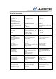
WashTec International Aegypten / رصم Bosnien-Herzegovina / Bosna i Hercegovina Griechenland / Ελλάδα D. Alexandratos & Sons, S.A. Mesologiou 100 185 46 Piraeus Ferrum Egypt 8 M. Youssef Selim Street Cairo Algerien / رئازجلا Bulgarien / България Großbritannien / UK TopNet Hai Ain Al-Soltane Les Vergers/Birkhadern Alger Euromarket Industrial Autoservice Equipment J.S. Co 51 Andrei Liaptechv blvd. Mladost - 1 1784 Sofia, Bulgaria WashTec UK Ltd. 14 Oak Industrial Estate Chelmsford Rd.
WashTec International Kanar. Inseln / Islas Canarias Litauen / Lietuva Norwegen / Norge Dican Auto D.M., SL C/Ferrallista n° 11 Polignono Industrial Salinetas, Parcela 36 E-35219 Telde Las Palmas - Gran Canaria Cosmica Servisas Ltd. H. ir O. Mionkovskiu 87, LT - 46222, Kaunas WashTec Bilvask Bedriftsveien 6 N - 0950 Oslo Kasachstan/ Қазақстан Luxemburg / Luxembourg Oman / نامع Atameken TransService TOO Gagarin Str. 236-B Almaty spk s.a.
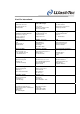
WashTec International Rumänien / România ACIS Petrolservice Srl. Str. Gábor Áron Nr. 20 Vlahita-535800 Serbien-Montenegro / Serbia & Montenegro Tecon Sistem Proleterske solidarnosti 21b 11070 Novi Beograd Ukraine / Україна DP "ACIS-Ukraine" Kharkovskaya road 201/203 02091, Kyiv, Ukraine Rumänien / România Singapur / Singapore Ungarn / Magyarország PRO WASH DISTRIBUTION SRL Bd. Preciziei, 1 etaj 3-D Tronson 1 Sector 6 052202 Bucharest Kims Marketing Pte Ltd.
Dear Customer, thank you for opting for WashTec. You have selected a product that will be in reliable operation in your car wash business for a long time. And there is a lot you can do to ensure this. Please read this operating manual carefully and observe the maintenance and care instructions listed in it. This significantly increases the service life of your system.
Exclusions from warranty Valid for machine types: GW z Delivery and installation of any type of illuminates and lights X z Delivery and installation of sign boards or –foils.
Valid for machine types: GW Services which have to be supplied to remedy or minimize, X odour problems and which have been caused by insufficient 13. cleaning of the recycling system and its environment 14. 15. 16. 17. 18.
List of contents Subject Page no. Introduction 1. General information 1.1. 1.2. Guide to symbols Declaration of conformity 2. Safety instructions 2.1. 2.2. 2.3. 2.4. 2.5. 1-1 1-1 1-1 2-1 General information Intended use Additional dangers Working safely Safety during operation 2-1 2-2 2-3 2-3 2-6 3. Structure and function 3-1 3.1. Mechanical structure 3.2. Additional equipment - mechanical 3.3. Fluid technical system 3.3.1. Fluid system 3.3.2. Spray system 3.4. Control system and electronics 3.5.
6. Settings and checking 6.1. 6.2. 6.3. 6.4. 6.5. 6.6. Adjusting the compressed air Bleeding the suction lines at the dosing pumps Adjusting the dosing pump Bleeding the suction lines at the rim cleaner pump Adjust rim cleaner pump Reading and setting the water flowing pressure 7. Maintenance and care 7.1. Safety instructions 7.2. Care 7.2.1. Lime-scale removal 7.2.2. Cleaning of the system 7.2.3. Cleaning of the floor 7.2.4. Cleaning of plastic parts 7.2.5. Cleaning of the brushes 7.2.6.
10. Special equipment 10.1. 10.2. 10.3. 10.4. 10.5. 11. Technical specifications 11.1. 11.2. 12.
Chapter 1 – General information 1. General information 1.1. Guide to symbols This section contains an explanation of the symbols used in these operating instructions. Indicates an imminently hazardous situation which, if not avoided, may result in death or serious injury. CAUTION Indicates a potentially hazardous situation which, if not avoided, may result in property damage. NOTICE Indicates sections which contain important information. ) ⇒ Indicates work operations which need to be carried out.
Chapter 2 - Safety instructions 2. Safety instructions 2.1. General information In order to guarantee safe use and fault-free operation, all individuals who are involved in any way with the roll-over car wash system must have read and understood this operating manual. The instructions in this operating manual must be complied with by all individuals who operate the roll-over car wash system or who work on it.
Chapter 2 - Safety instructions 2.2. Intended use The roll-over car wash system is designed for cleaning the outside of closed vehicles or parts of vehicles, in which the cleaning, drying or special treatment equipment are power driven. CAUTION Vehicles which extend beyond the allowed vehicle-width or vehicle-length should not be washed. Pay attention to the information in chapter 11 "Technical specifications".
Chapter 2 - Safety instructions 2.3. Additional dangers The roll-over car wash system has been manufactured in accordance with the latest safety standards and has been rated as absolutely operationally safe. Despite this fact, the system can represent a danger if it is used incorrectly or for any purpose other than its intended use by untrained personnel. No liability can be accepted for damages caused by improper use, incorrect operation or non-observance of the operating instructions 2.4.
Chapter 2 - Safety instructions Working without protective clothes can cause serious accidents. Protective clothes ) ) ) Maintenance Service Care Observe the accident prevention regulations which apply to the place of operation. Wear proper non-skid boots, protective goggles and appropriate protective clothes. Maintenance, service and care work carried out on the machine while it is switched on can cause serious accidents.
Chapter 2 - Safety instructions Checks Faults Carrying out checking and adjustment work and attempting to rectify errors on the roll-over car wash system while it is switched on can result in serious accidents. If necessary, authorised, qualified and instructed individuals who are familiar with the potential risks may enter the system while it is switched on. In this case, there must always be a second person at the main switch who can switch off the roll-over car wash system in the event of an emergency.
Chapter 2 - Safety instructions 2.5. Safety during operation Safety instructions for the operator The roll-over car wash system may only be operated by authorised, qualified and instructed personnel. These individuals must have received instruction from WashTec Service personnel about potential dangers.
Chapter 2 - Safety instructions Incorrect use of the roll-over car wash system by customers can cause serious accidents. Safety instructions for the customer Only for car wash systems, where the customer remains in his car during the wash cycle Only for car wash systems, where the customer leaves his car during the wash cycle SoftCare Evo - Type SE10 Customers must be informed of the following without fail: For safety reasons, the instructions of the car wash plant operator must be obeyed.
Chapter 3 - Structure and function 3. Structure and function This chapter is designed to help you familiarise yourself with the structure and function of your roll-over car wash system. The following pages contain a short description of the individual assemblies, to assist you in this process: Mechanical structure ............................. Additional equipment - mechanical ..….. Fluid technical system ..........………...... Control system and electronics .............
Chapter 3 - Structure and function 3.1. Mechanical structure 1 = Frame 3 = Roof brush 5 = Wheel washer (option) 2 = Drier system 4 = Side brushes 6 = Operating unit Fig. 3-2: Roll-over car wash system- front view Frame SoftCare Evo - Type SE10 The self-supporting and galvanised sheet-steel frame forms the main framework of the roll-over car wash system. The two side elements contain the control cabinet on the right and the fluid technical system on the left side.
Chapter 3 - Structure and function Roof brush Up and down movements are executed steplessly by means of flat belts and the lift drive. 2 3 1 1 = Shaft 2 = Rotary drive 3 = Flat belt Fig. 3-3: Roof brush During the wash stage, the vehicle contour is memorised. The central control system regulates the up and down movement based on this data. Before the drying starts, the roof brush is switched on to remove remaining water out of the brush.
Chapter 3 - Structure and function Side brushes The side brushes are connected directly to the rotary drive by rollers. The side brushes are mounted on a moving bearing for precise adaptation to the vehicle contours. Fig. 3-4: Side brushes on movable bearings During the wash stage, the vehicle contour is memorised. The microprocessor control system regulates the position and consequently the application pressure of the side brushes on the basis of these measured data.
Chapter 3 - Structure and function Drier system The drier system is made up of the two side nozzles and the two side blowers (1) as well as a roof nozzle with an integrated blower (2). Optionally the roof nozzle may be swivel-mounted (see Chapter 3.2. “Additional equipment - mechanical“). The roof nozzle is mounted on guide rails. Up and down movements are executed steplessly by means of two flat belts on each side and the lift drive. 1 = Side blowers 2 = Roof nozzle with integrated blower Fig.
Chapter 3 - Structure and function Safety ring switch There is a safety ring switch (1) located at the centre of the nozzle. As soon as the safety ring switch touches a vehicle during the drying stage, the gantry is stopped and the roof nozzle makes a correcting movement (upwards). If the safety ring switch is thereby not released the system is switched off. The display on the operating terminal shows an error message.
Chapter 3 - Structure and function 3.2. Additional equipment - mechanical Depending on the model, your roll-over car wash system will have various kinds of additional equipment. Wheel washer One of the following wheel washers may be installed in the system: Low-pressure brush wheel washer 18“ rims. Horizontally guided. Directly driven. High-pressure brush wheel washer for 18“ rims. Horizontally guided. Directly driven. Fig.
Chapter 3 - Structure and function The wheel wash brushes are integrated in both side elements and are driven directly. A light barrier (1) identifies the wheel. 1 = Light barrier Fig.
Chapter 3 - Structure and function Swivel mounted and rotating roof nozzle The swivel mounted and the rotating roof nozzle improves the drying result. Swivel-mounted roof nozzle: A pneumatically controlled cylinder (1) swivels the nozzle towards the front or rear of the vehicle. 1 = Pneumatically controlled cylinder Fig.
Chapter 3 - Structure and function Roof nozzle with light barrier system The light barrier system at the roof nozzle serves two functions: 1. Contour control When a vehicle has not yet been captured by the brush wash the light barrier system controls the up and down movement of the roof nozzle. 2. Safety function The light barriers serve as an additional safety device to the safety ring switch. 1 1 = Light barriers Fig.
Chapter 3 - Structure and function ! Defect light-barriers can cause damage to vehicles. ) Observe the operating unit for failure messages during start-up of the system. Obstacles on the vehicle (taxi signs, ski-holders, etc.) may not, in some circumstances, be detected, and can be damaged. ) SoftCare Evo - Type SE10 Override obstacles manually (see chapter 9, "Operating units").
Chapter 3 - Structure and function Positioning aid and traffic light Positioning of the vehicle in the wash hall is supported by a light barrier system and a traffic light in the side element. Two light barriers (1) and (2) identify the position of the vehicle. Fig. 3-11: Position of the traffic-light light barriers The symbols for positioning the vehicle are actuated by the light barriers, e.g.: FORWARD S T O P STOP REVERSE Fig.
Chapter 3 - Structure and function Insufficient safety distances may cause severe accidents. Systems where the safety distance does not comply with local regulations may not be operated without safety shutdowns. In case the system has been modified afterwards in a way that the safety distance does not comply anymore with local regulations (i.e. installation of a heater, a wash basin, etc.) the wash system has to be refitted with a safety shutdown.
Chapter 3 - Structure and function Safety shutdown rear side The safety shutdown at the rear side consists of a u-profile (2) which is mounted above the guidance rail of the roof nozzle. The u-profile is swivel mounted and fastened by a bolt with a spring at the bottom. A switch (1) is located behind the u-profile. The system shuts down as soon as frontal pressure is applied to the u-profile. 1 2 1 = Switch 2 = U-profile Fig.
Chapter 3 - Structure and function Outer sides The safety shutdown at the outer sides consists of a swivel mounted splash guard and a switch which is mounted behind the splash guard in the lower section. The system shuts down as soon as pressure is applied to the splash guard. Fig. 3-15: Safety shutdown outer sides If the safety shutdown is faulty, people can get caught between the wall of the building and the wash gantry.
Chapter 3 - Structure and function 3.3. Fluid technical system The fluid technical system is made up of the following elements: Fluid system Spray system Fluid system Spray system 1 = Low pressure water distribution 2 = Pneumatic system 3 = Dosing pumps and cleaning agent containers Fig.
Chapter 3 - Structure and function 3.3.1. Fluid system CAUTION A modification of the water and air pressure settings may cause damage to the system and/or vehicle and/or a deterioration of the washing result. Change settings only in agreement with WashTec. Low-pressure water distribution The low-pressure water distribution (see figure 3-18) distributes the fresh and process water through the outlets to the individual spray systems.
Chapter 3 - Structure and function Inlet Process water side (A) Outlet Inlet Fresh water side (B) Outlet 1a = 1b = 2= 3a = 3b = 4= Process water inlet with winter control Process water inlet w/o winter control Pre-rinsing Brush wetting standard Brush wetting with dryrun protection Low-pressure wheel washer 5a = 5b= 5c= 5d= 6= 7= 8= 9= 10 = 11 = Fresh water with osmosis w/o winter control Fresh water with osmosis with winter control Fresh water w/o osmosis w/o winter control Fresh water w/o osmosis wi
Chapter 3 - Structure and function Dosing pumps and cleaning agent containers NOTICE The pneumatically controlled dosing pumps draw the cleaning and care products from the relevant cleaning agent containers and lead them to the injection points in the low-pressure water distribution. See chapter 6 for information about adjusting and bleeding the dosing pumps. See chapter 4 for refilling the cleaning agent containers.
Chapter 3 - Structure and function Pneumatic system The main connection for the customer supplied compressed air is located a the filter pressure regulator (1a). The compressed air supply is controlled by a ball valve (1b). Only oil-free compressed air is permitted. The filter pressure regulator cleans the compressed air from destructive particles and regulates the compressed air which is provided by the customer to the main pressure of approx. 6 bar. Fig.
Chapter 3 - Structure and function Heater and freeze protection device The heater (1+2) in the media cabinet guarantees a safe operation during low temperatures. A temperature sensor controls the temperature in the cabinet. If the temperature drops 2° below the temperature setpoint the heater is switched on automatically. Temperature setting with service program menu 0371 (see chapter 9.6).
Chapter 3 - Structure and function 3.3.2. Spray system Depending on the configuration your roll-over car wash system may be equipped with a varying number of spray heads and spray pipes. The spray pipes are connected with hoses to the water distribution Spray system - options Spray system - standard 1a 1b 2 3 4 5 6 7 8 = = = = = = = = = Pre-and post-rinsing Post-rinsing Brush wetting Preservation Foam pre-wash Side high-pressure Chemical pre-wash Rim cleaning device Roof high-pressure Fig.
Chapter 3 - Structure and function Standard spray system Pre-rinsing (1a) Removes coarse dirt. Depending on the configuration with process water or fresh water. Post-rinsing (1a + 1b) Rinses the washed vehicle with fresh water. NOTICE Water pressure for post rinsing is adjustable at separate ball valve. Do not reduce the flowing pressure at the fresh water inlet because this will also change the mixing ratio of the foam system. Brush wetting (2) 1.
Chapter 3 - Structure and function Optional spray system Foam pre-wash (4) The foam device sprays a dirt- softening, highly foaming shampoo onto the surface of the vehicle during a separate stage. NOTICE The best cleaning result is achieved with liquid and fine blowy foam which flows down the vehicle. Dry foam does not absorb the dirt and has only a limited cleaning effect (see chapter 6 „Operation and settings“ for more information).
Chapter 3 - Structure and function Osmosis The osmosis device takes care of a stainless drying of the vehicle when no dryer system is installed. During post-rinsing it sprays the vehicle with osmosis water instead of fresh water. At the same time a chemical drying aid may be applied. Rim spraying device (7) The rim spraying device applies a rim cleaner through a nozzle as soon as the wheel is detected by the light barrier.
Chapter 3 - Structure and function High-pressure spray system The high-pressure spray system is of modular structure and consists of a side and a roof high-pressure system which may be combined. The high-pressure spray system cleans the vehicle with high water pressure from coarse dirt. Depending on the configuration with fresh or process water.
Chapter 3 - Structure and function 3.4. Control system and electronics The control system is installed in control cabinet. 1 = Microprocessor control 2 = Transformer 3 = Lamp module 4 = Fuses 5 = Motor protection switches 7 = Conductors 8 = Frequency converters Fig.
Chapter 3 - Structure and function When the control cabinet door is opened, there is a risk of electrical shock injury when the system is switched on. Switch the power off at the main switch before you open the control cabinet door.
Chapter 3 - Structure and function 3.5. Special equipment Depending on the model, your roll-over car wash system may have an additional fresh water supply an under-body-wash a rolling shutter door control system … You can find a detailed description of all the above in Chapter 10 "Special equipment".
Chapter 4 – Commissioning/dismantling/ conversion/ transport/assembly 4. Commissioning/assembly/dismantling/conversion/disposal 4.1. Commissioning This chapter describes all the stages which must be worked through daily in order to put the roll-over car wash system into operation correctly. Cleaning work ) ) CAUTION Clean the floor of the building. Take particular care over the area around the floor rails.
Chapter 4 – Commissioning/dismantling/ conversion/ transport/assembly There is a risk of injury in frosty conditions by ice formations in the entrance and exit area. Remove the ice from the entrance and exit area. Check brushes ) ) CAUTION Check all brushes for foreign parts (dirt, small stones, etc.) and remove them if necessary. Check all brushes for a tight fitting. Foreign parts in the brushes and brushes which are not securely tightened may damage the vehicle.
Chapter 4 – Commissioning/dismantling/ conversion/ transport/assembly Cleaning agents ) ) Check the levels in the chemical storage containers. If necessary, fill up the containers with cleaning agent, pre-diluted as recommended by the supplier of the cleaning agents. If a chemical storage container has been emptied completely, all air must be bled out of the supply lead (see Chapter 6 "Operation and settings"). There is a risk of injury when the system is switched on.
Chapter 4 – Commissioning/dismantling/ conversion/ transport/assembly Caution should be exercised in handling all chemical compounds. Some car wash chemicals are somewhat caustic and should not be permitted to come in direct contact with bare skins or eyes. ) ) CAUTION Always refer to product MSDS Sheets for proper precautions. Whenever handling such chemicals wear proper protective rubber gloves, boots and a face shield.
Chapter 4 – Commissioning/dismantling/ conversion/ transport/assembly Safety devices A fault in the safety devices (emergency-off function, safety shut-down and safety switches) can cause serious accidents and/or damage to vehicles. For this reason, all safety devices must be checked every day to ensure that they function correctly. If any safety device is faulty, please inform WashTec Service immediately. On no account may the roll-over car wash system be put into operation.
Chapter 4 – Commissioning/dismantling/ conversion/ transport/assembly Checking safety switch on side brushes ) Push one of the side brushes strongly backward. ⇒ The display in the operating unit shows „Safety strip actuated“. ⇒ The message remains in the display after releasing the side brush. ) ) Checking the safety shutdown Acknowledge the message. Repeat the above steps for the other side brush.
Chapter 4 – Commissioning/dismantling/ conversion/ transport/assembly ) Press frontal against the u-profile located above the guidance rail. ⇒ The display in the operating unit shows „Emergency stop actuated internally“. ⇒ The message remains in the display after releasing the u-profile. ) ) ) Acknowledge the message. Repeat the above steps for the second uprofile. Press frontal against the lateral splash guard. ⇒ The display in the operating unit shows „Emergency stop actuated internally“.
Chapter 4 – Commissioning/dismantling/ conversion/ transport/assembly Checking the positioning aid If your roll-over car wash system is equipped with a positioning aid, it must be tested by covering the light barriers before the system is put into operation. If they function correctly, the following symbols should be illuminated: ) Both light barriers free: ⇒ The traffic light shows "FORWARD" = arrow flashes. ) Cover light barrier 1. ⇒ The traffic light shows "STOP". ) Cover light barriers 1 and 2.
Chapter 4 – Commissioning/dismantling/ conversion/ transport/assembly We can accept no liability for damage caused by dismantling, transportation or reconstruction or by conversion work carried out on the roll-over car wash system. This applies also for disposal of the roll-over car wash system. 4.2.
Chapter 5 - Washing operation 5. Washing operation This chapter contains important safety instructions for washing operation and describes all the stages which must be worked through when washing vehicles. NOTICE This information is intended for the wash system operator and for car wash customers. The car wash customer must be fully informed on instruction notices. Instructions which are intended only for the wash system operator are marked separately. 5.1.
Chapter 5 - Washing operation CAUTION If the roll-over car wash system is used for vehicles with certain features, this may result in damage to the vehicle. The customer has to be informed unconditionally about the following topics: SoftCare Evo - Type SE10 Vehicles which are not suitable for the dimensions of the roll-over car wash system (see Chapter 11 "Technical specifications") may not be washed.
Chapter 5 - Washing operation NOTICE Information only for the operator WashTec can accept no responsibility for damage to vehicles where one or more of the points listed above are applicable. If these vehicles are washed irrespective of the above points, this must be done on the good judgement of the operator and will be his responsibility.
Chapter 5 - Washing operation 5.2. Preparing the vehicle In order to prevent damage to vehicles, the following preparations must be made before washing. These preparations can be made either by the wash plant operator or the customer. The customer has to be informed unconditionally about the following topics: ) ) ) ) ) ) ) ) ) Remove aerials or push them in. Switch off radios if the vehicle is equipped with an automatic aerial. Fold in the mirrors if possible. Remove any extra mirrors.
Chapter 5 - Washing operation 5.3. Car wash procedure The car wash procedure depends on the selected start setting (see chapter 9.6. menu 035 Automatic start), on the setting of the entrance/exit doors (see chapter 9.6. menu 033 door functions) and whether the driver remains in the vehicle during the wash cycle or waits outside of the wash building. Three typical car wash procedures are described below.
Chapter 5 - Washing operation Operation mode 2 Automatic start is switched off, the entrance door is closed and the driver waits outside of the wash building. ) ⇒ ) ) ⇒ ) ) ) ) ⇒ ⇒ ⇒ ) CAUTION SoftCare Evo - Type SE10 Select a wash program (by card or by input at the operating unit). The entrance door opens Drive the vehicle forward into the wash system so that there is enough space on each side. Position the vehicle correctly The traffic light shows “Stop”.
Chapter 5 - Washing operation Operation mode 3 Automatic start is switched on, the entrance door is closed and the driver remains in the vehicle during the wash cycle. ) ⇒ ) ) ) ⇒ ) ) Select a wash program (by card or by input at the operating unit). The entrance door opens Close windows and doors and lock all doors from the inside. Drive the vehicle forward into the wash system so that there is enough space on each side. Position the vehicle correctly The traffic light shows “Stop”.
Chapter 5 - Washing operation 5.4. Procedure for emergency stops and malfunctions CAUTION Information only for the operator! Depending on the cause of the emergency stop or the malfunction you may continue or terminate the wash after the cause of the malfunction has been fixed. Vehicle and/or wash system may be damaged if the wash is continued without fixing the cause of the emergency stop or the malfunction.
Chapter 5 - Washing operation Non-observance of the safety instructions may cause severe accidents. Observe always the safety instructions in chapter 2. ) Step 1 Check whether the vehicle and/or the wash system have been damaged. Continue with step 5 if the vehicle and/or the wash system have been damaged. ) Step 2 ) NOTICE Step 3 Check if you can fix the cause of the emergency stop or the malfunction by yourself.
Chapter 5 - Washing operation The LEDs in the buttons <> and <> flash alternately after the cause of the emergency stop or malfunction has been fixed. Step 4 Continue wash You may now continue or terminate the wash. Continue with step 6 if you would like to terminate the wash. ) Press the button at the operating unit. ⇒ The wash program will be continued. NOTICE Watch the further wash procedure.
Chapter 5 - Washing operation ) ) Ascertain the reason for the emergency-stop/ malfunction. Check if you can fix the cause of the emergency stop or the malfunction by yourself. Continue with step 7 if you cannot fix the cause of the emergency stop or malfunction by yourself. ) ) ⇒ Step 6 Move system in home position ) ) ) ) ⇒ ) SoftCare Evo - Type SE10 Fix the cause of the emergency stop or malfunction. Release the emergency-off button (if actuated).
Chapter 5 - Washing operation Step 7 Move system with malfunction in home position If you cannot fix the cause for the emergency stop or the malfunction the failure cannot be acknowledged. However you may move the system in home position under certain conditions. ) ) ) ⇒ ) Step 8 ) ) SoftCare Evo - Type SE10 Check if the roll-over car wash system can be moved in home position without further damage to the vehicle. Release the emergency-off button (if actuated).
Chapter 6 – Settings and checking 6. Settings and checking Adjustments at a system which is switched on may cause serious accidents. Pay unconditional attention to the safety instructions in chapter 2. 6.1. Adjusting the compressed air Main pressure The filter pressure regulator cleans the compressed air from destructive particles and regulates the main pressure. 3 1 2 7 4 Set-value main pressure: approx. 6 bar. The ball valve (7) is used to control the supply of compressed air.
Chapter 6 – Settings and checking Reduced pressure Several pneumatic components (e.g. wheel washer) and the foam spray systems are operated with reduced air pressure. This pressure is adjusted at the according pressure regulators. The illustration below shows the position of the pressure regulators at maximum configuration. The location of the pressure regulators changes if less pressure regulators are installed (e.g. no foamed chemical pre-wash).
Chapter 6 – Settings and checking The air pressure is adjusted by the control knob. ) ) ) Release the regulator by pulling the knob downwards. Set the required pressure by turning the knob to the right or to the left. Secure the regulator by pushing the knob upwards. Fig. 6-2: Adjusting air pressure NOTICE Reading and setting of the air pressure for foam spray systems is only possible when the spray system is switched on.
Chapter 6 - Operation and settings 6.2. Bleeding the suction lines at the dosing pumps If a cleaning agent container has been emptied completely, all air must be bled out of the suction line after the container has been refilled. 1 = Suction line from cleaning agent container 2 = Supply line to injection point 3 = Bleed line 2 ) Turn the bleeder lever to the left to „Bleeding“ = arrow downwards.
Chapter 6 - Operation and settings 6.3. Adjusting the dosing pump The required volume of chemical agent depends on the type of chemical agent. Please follow the detergent manufacturer's instructions. Release the click-stop by pulling out the adjuster and adjust to the delivery volume recommended by the supplier. Push in the adjuster afterwards. CAUTION The adjustment of the volume may only be done during operation of the dosing pump.
Chapter 6 - Operation and settings 6.4. Bleeding the suction lines at the rim cleaner pump If a cleaning agent container has been emptied completely, all air must be bled out of the suction line after the container has been refilled. ) Switch on the dosing pump by using the menu 039 in the service program (see chapter 9.6. “Service program – program menus”). In condition „rim cleaner pump on“ the pump will be clocked, i.e. with each stroke cleaning agent is drawn out of the container.
Chapter 6 - Operation and settings 6.5. Adjust rim cleaner pump The volume of chemical agent required depends on the type of chemical agent. Please follow the detergent manufacturer's instructions. ) Adjust the delivery volume at the adjusting screw (1) at the rim cleaner pump.
Chapter 6 - Operation and settings 6.6. Reading and setting the water flowing pressure The water flowing pressure can be read of at the pressure gauges (2) and can be adjusted at the pressure regulators (1). NOTICE The water flowing pressure has been optimally adjusted by WashTec Service during initial commissioning of the system. A modification of the settings may cause a deterioration of the washing result. 1 = Pressure regulator 2 = Pressure gauge Fig.
Chapter 6 - Operation and settings Water flow pressure for process water- / fresh water supply and for fresh water supply at systems without foam system ) ) ) Switch on a spray arch which is supplied with process water, e.g. pre-rinsing, by using the menu 038 in the service program (see chapter 9.6. “Service program – program menus”). Read off the flowing pressure at the pressure gauge. Readjust the setting if necessary at the pressure regulator. Set value with spray system is switched on: 3 bar.
Chapter 7 - Maintenance and care 7. Maintenance and care 7.1. Safety instructions Maintenance, service and care work carried out on the machine while it is switched on can cause serious accidents. Always work through the following steps before starting maintenance, service and care work: ) ) ) ) ) CAUTION Switch off the electricity on the complete system Turn off the compressed air.
Chapter 7 - Maintenance and care 7.2. Care Regular care of the roll-over car wash system contributes considerably to its smooth running and helps retain its value. The essential care programme includes: Lime-scale removal Cleaning of the system Cleaning of the floor Cleaning of the brushes Special treatment The care intervals depend on the water quality and the degree of soiling. Caution should be exercised in handling all chemical compounds.
Chapter 7 - Maintenance and care CAUTION Cleaning with high pressure may cause damage to the roll-over car wash system. Do not use high pressure appliances for cleaning.
Chapter 7 - Maintenance and care 7.2.1. Lime-scale removal Sooner or later, depending on the water quality, limescale deposits will build up on the system. These must be removed carefully. ) ) ) ) CAUTION Only use products for lime-scale removal that are based on citric acid, amidosulphuric acid or phosphoric acid. Mix these with water in the proportions specified by the manufacturer. Use these products to remove the lime-scale deposits carefully from the system.
Chapter 7 - Maintenance and care 7.2.2. Cleaning of the system ) ) Clean the entire frame of the roll-over car wash system. Clean the flat belts of the lifting system of roof brush and drier system. Only use pH-neutral cleaning and treatment products for this purpose (see below) or the cleaning agent that is also used for cleaning vehicles in the prescribed concentration. ) CAUTION Rinse the system down with plenty clear water.
Chapter 7 - Maintenance and care 7.2.4. Cleaning of plastic parts CAUTION Plastic parts (claddings, displays, etc.) may be damaged or scratched when they are cleaned with rough surfaces (e.g. brushes) or when they are dry cleaned. Clean plastic parts only with wet soft clothes or sponges. 7.2.5. Cleaning of the brushes The following description applies to the cleaning of original WashTec brushes. Water hardness The water hardness has substantial influence on the type of pollution.
Chapter 7 - Maintenance and care The information and conversion table below should assist you in the definition: Specification in hardness grades: French hardness: 1 °dH = 1,78 °fH 1 ° fH = 0,56 °dH English hardness: 1 °dH = 1,25 °eH 1 ° eH = 0,8 °dH Specification in calcium and magnesium ions: 10 °dH = 1,8 mmol/l Ca + Mg If calcium and magnesium are specified in mg/l use the conversion below: 1 mg/l calcium = 0,025 mmol/l calcium 1 mg/l magnesium = 0,043 mmol/l magnesium CAUTION Brushes may be damaged
Chapter 7 - Maintenance and care Clean the brushes first with an acid cleaner (cleaner with a pH value < 7) if the water hardness is higher then 10 ° dH,. If the water hardness is lower you can start immediately with the alkaline cleaning (pH-value > 7). Acid cleaning ) ) ) Alkaline cleaning ) ) ) Final work ) ) SoftCare Evo - Type SE10 Spray the brushes with acid cleaner. Let the cleaner act on the brushes for approx. 10-15 min.
Chapter 7 - Maintenance and care 7.2.6. Special treatment Rollover maintenance should be completed with the application of a protective coating. Treatment can be carried out with commercially available treatment products that are water repellent and form an invisible protective film. ) ) NOTICE Apply the treatment product to the frame of the roll-over car wash system. Rub off any extra treatment product. Exercise caution when using treatment products.
Chapter 7 - Maintenance and care 7.3. Maintenance Your roll-over car wash system has been developed and manufactured so that a minimum of maintenance and care work is necessary. In order to ensure that constantly good washing results and the maximum system operating time are always achieved, you should carry out the following work on a regular basis. You can find a check-list for maintenance and care work in the appendix. Please use this list as a reminder when carrying out the necessary work. 7.3.1.
Chapter 7 - Maintenance and care 7.3.2. Weekly Maintenance Flat belt ) Check the belts for deterioration and wear. If there is a high degree of deterioration or wear, i.e. the belts are frayed, ripped or fragile, please inform WashTec Service. Operation with damaged belts may cause serious injury to persons or damage to the vehicle. Pay attention to the safety instructions in chapter 2.
Chapter 7 - Maintenance and care 7.3.3. Monthly Maintenance Cleaning agent containers ) ) ) Checking brushes Track and guide rollers SoftCare Evo - Type SE10 ) ) ) Rinse out the cleaning agent containers with water to remove any thickened chemicals. Fill each container with the correct cleaning agent. Bleed all air out of the supply hoses (see Chapter 6 "Operation and settings") Check the side and roof brushes and wheel washing brushes for wear.
Chapter 7 - Maintenance and care 7.3.4. Maintenance every six months Safety ring switch Slide bearings NOTICE ) ) ) NOTICE SoftCare Evo - Type SE10 Spray the guide of the safety ring switch with the WashTec special-grease-spray. Spray all slide bearings with the WashTec special-grease-spray. Use the WashTec special-grease-spray with caution: do not spray into the wash brushes. ) Drives Check the safety ring switch for smooth operation. Ensure that all the drives are properly sealed.
Chapter 7 - Maintenance and care 7.3.5. Annually We recommend an annual inspection of the highpressure system and of the safety devices by WashTec Service. NOTICE Check whether your roll-over car wash system is fitted with additional equipment. If this is the case, please also carry out the required maintenance and care work for these appliances. You can find a detailed description in Chapter 10 "Special equipment" or in the separate operating instructions of the appliances.
Chapter 8 - Error messages 8. Error messages The error messages will be shown in the display of the operating unit according to the pattern shown below: Part Failure Module name No. Type of failure DB1 S15 025 No travel pulses Pulse counter DD1 B4 039 Short circuit transmitter Light barrier front 061 Safety strip initiated Emergency-off CHK Cause of failure The module abbreviation shows the module where the failure has been occurred, for example DB1 = roof brush.
Chapter 8 - Error messages Modules, type of failure and cause of failure are combined by the controller and displayed on the operating unit. Example: Procedure at error messages Part Failure Module name No. Type of failure DB1 S14 002 Stop position not disconnected Upper limit switch DD1 S19 002 Stop position not disconnected Upper limit switch ) ) SoftCare Evo - Type SE10 Cause of failure Read off the error message on the operating unit and make notice of the message.
Chapter 8 - Error messages Table of modules – part 1 Abbreviation Module DB1 SB1 SB2 RAW DD1 UBW Q1 C2 C3 C4 C5 C6 C7 Q9 Q10 Q50 Q1 Q52 Q53 Q25 Q27 Q54 Q37 Q38 Q44 Q13 Q43 Q55 Q56 DOP PMP ANL M1 M2 M3 SoftCare Evo - Type SE10 Roof brush 1 Side brush 1 Side brush 2 Wheel wash brush Roof nozzle 1 Under-body wash Pre-rinsing Brush wetting Foam CVW Wax Post-rinsing / CTH Special chemistry with foam Special chemistry without foam Hot water Cold water Chemical pre-wash bumper Chemical pre-wash lower side Chem
Chapter 8 - Error messages Table of modules – part 2 Abbreviation Module CHK FUP FUH FS1 FS2 WAB EFT AFT TTO KLG LED PVS RPD SER BED KFZ LS TST SOF SoftCare Evo - Type SE10 Check, monitoring Frequency converter gantry Frequency converter lifting Frequency converter side brush 1 Frequency converter side brush 2 Vehicle moving device Entrance door Exit door Separation door Card reader unit LED display Peripheral distributor cabinet Real Power Device, Effective power measurement device Serial interfaces Op
Chapter 8 - Error messages Type of failure and cause of failure – Part 1 No.
Chapter 8 - Error messages Type of failure and cause of failure – Part 2 No.
Chapter 8 - Error messages Type of failure and cause of failure – Part 3 No.
Chapter 8 - Error messages Type of failure and cause of failure – Part 4 No.
Chapter 8 - Error messages Type of failure and cause of failure – Part 5 No.
Chapter 8 - Error messages Type of failure and cause of failure – Part 6 No.
Chapter 9 - Operating units 9. Operating units The roll-over car wash system can be operated, i.e. starting the wash programs and making adjustments, with various different operating units. The roll-over car wash system is always equipped with an operating terminal of type CP1 or CP0. Wash programs can be started from the operating terminal by pressing a program button or by entering a code. The operating terminal CP1 may be equipped with a multifunctional unit (option).
Chapter 9 - Operating units Instead of the optional card reader other card readers may be installed. From these card readers wash programs may be started by using punched-cards, magnetic cards or transponder cards. These card readers are described in separate operating instructions.
Chapter 9 - Operating units Check which type of operating terminal is used in your system and turn to the relevant chapter or read the individual operating instructions. Operating terminal CP1.................................... 9-4 Operating terminal CP0…………….......……… 9-6 Start-up of the terminal...................................... 9-9 Start of wash programs.................................... 9-9 Manual operation with control buttons............. 9-12 Service programs..................................
Chapter 9 - Operating units 9.1. Operating terminal CP1 The operating terminal CP1 is used to control the wash system. It is installed in a plastic housing which can be wall-mounted or rack-mounted. 1 = Display 2 = Numeric keys 3 = Control buttons 4 = Special function buttons 5 = Function buttons 6 = Navigation buttons 7 = Emergency-Off button Fig.
Chapter 9 - Operating units Numeric keys Numeric keys are used to select programs and to enter data in the service programs. Control buttons Control buttons are used for manual operation of individual machine elements such as roof brush, side brushes, etc. Special function buttons The buttons F1 – F3 are used to start special functions which have been previously assigned by WashTec Service. The button P is used to start the service program. Function buttons The button <> is used to acknowledge inputs.
Chapter 9 - Operating units 9.2. Operating terminal CP0 The operating terminal CP0 is used to control the wash system. It is installed in a plastic housing which can be wall-mounted or integrated in a door cut-out. 1 = Display 2 = Numeric keys 3 = Selection buttons 4 = Function buttons 5 = Navigation buttons 6 = Emergency-Off button Fig. 9-3: Operating terminal CP0 - front view The contrast of the display may be adjusted at the operating terminal anytime.
Chapter 9 - Operating units Numeric keys Numeric keys are used to select programs and to enter data in the service programs. Selection buttons The lowest line of the display shows up to four symbols: Fig. 9-4: Display of symbols Symbols for manual operation Symbols for special functions Symbol for starting the service program Fig. 9-5: Symbols SoftCare Evo - Type SE10 Use the buttons <<§>> and <<¨>> to display further symbols. All available symbols are shown on the left side.
Chapter 9 - Operating units Use the selection buttons F1 to F4 to select the according symbol. A selected symbol is marked with a black background. Function buttons The button <> is used to acknowledge inputs. The button <> is used to cancel inputs. The button <> is used to start wash programs. Navigation buttons The navigation buttons are used to select the symbols, the direction of motion of the machine elements during manual operation and to navigate within service program menus.
Chapter 9 - Operating units 9.3. Starting up the operating terminal The operating terminal is started automatically when the roll-over car wash system is switched on at the main switch. Depending on the operation mode, the display may show one of the messages below: Drive in vehicle or Select program or Please insert card 9.4. Starting wash programs Wash programs may be started by entering a program number or a program code (code operation mode).
Chapter 9 - Operating units The further steps depend on the operation mode and the position of the vehicle. Operation mode 1 The driver drives into the wash building, positions the vehicle, leaves the vehicle, starts the wash program and waits outside of the building. Procedure ) ) ⇒ Select the desired wash program on the keypad or enter the code. Acknowledge the input with the button <> or press the button <> if you would like to change the input. The wash program starts.
Chapter 9 - Operating units Operation mode 2 The driver drives in front of the wash building, selects a wash program, drives the vehicle into the building, leaves the vehicle, starts the wash program and waits outside of the building. Procedure ) ) ) ) ⇒ Select the desired wash program on the keypad or enter the code. Acknowledge the input with the button <> or press the button << Cancel >> if you would like to change the input. Drive the vehicle into the building.
Chapter 9 - Operating units 9.5. Manual operation with the control buttons The control buttons can be used for manual operation of individual machine elements, such as the roof brush, side brushes, etc. or of the complete wash gantry. At the operating terminal CP 1 you can access the machine elements directly by pressing the according button.
Chapter 9 - Operating units Control mode During control mode, i.e. no wash program running, a machine element is only selected with a control button. This machine element can be moved into the desired direction by using the navigation buttons. ) ⇒ ) ⇒ Select the desired machine element by using the control buttons. At CP1: The LED in the lower right corner is illuminated At CP0: The symbol is marked with a black background Select the desired direction of movement by using the navigation buttons.
Chapter 9 - Operating units Control button <> + Wash mode: Roof brush up. The roof brush moves back downwards after releasing the button. Control mode: Roof brush up or down. The roof brush remains in its actual position after releasing the button. Control button <> + Wash mode: Side brushes apart. The side brushes moves back inwards after releasing the button. Control mode: Side brushes apart or together.
Chapter 9 - Operating units Control button <> + Wash mode: Without function. Control mode: Wash gantry forward or backward. The wash gantry remains in its position after releasing the button. Control button <> + Wash mode: Without function. Control mode: Roof brush and roof nozzle move upwards, side brushes move apart. The wash gantry moves in its home position.
Chapter 9 - Operating units 9.6. Service programs Service programs allow the manager or owner of the wash tunnel to modify designated settings of the system. Service programs are started by using the special function button <
>. At the operating terminal CP 1 you can start the service program directly by pressing the button <
>. At the operating terminal CP0 you probably have to shift the symbol “P” into the display by using the navigation buttons.
Chapter 9 - Operating units Access and Termination To access and terminate service programs follow the sequence as shown below.
Chapter 9 - Operating units NOTICE Service programs may not be accessed while wash programs are executed. Service programs are structured in several levels. In each level different operations can be performed. About using service programs NOTICE There is a button called <> on the front panel. The meaning of this button is Cancel or Abort. The menu items within a service program can be called by using the navigation buttons or by entering the menu item number directly.
Chapter 9 - Operating units Navigation with the service program with these buttons OK 0> Operator Button < > or leads to the next lower level Or Cancel Or 01> Wash counter OK 02> Invoicing Or Cancel A “>” behind the item number indicate that there is a lower menu level available Or 020> Accounting 03> Machine settings Button and call the previous or next menu item within a menu level OK 04> System settings Or Button < > or leads back to the next higher level Cancel Or 040> Date
Chapter 9 - Operating units Values/parameters can be modified within a menu item.
Chapter 9 - Operating units Service program menus The menu items of a service program are released by a password when accessing the service program. The following listing shows all menu items which may be called from the operator or the owner of the rollover car wash system. A menu item can be called directly by using the number code.
Chapter 9 - Operating units Menu 01> Wash counter The menu „Wash counter“ displays different counters. The table below shows at a glance all menus and sub-menus available in this menu item.
Chapter 9 - Operating units ) ⇒ Press the button <<¨>> to enter the next menu level. The display shows the first sub-menu 010 Total counter ) Menu 010 Total counter ) ⇒ Select the desired sub-menu by pressing the buttons <<ª>> and <<©>>. Press the button <<¨>> to display the total counter.
Chapter 9 - Operating units Menu 011 Lifetime ) ⇒ Press the button <<¨>> to enter the next menu level. The display shows the first sub-menu 0110 Cash (Manual entry) The menu „Lifetime“ provides three sub-menus ) Select the desired sub-menu by pressing the buttons <<ª>> and <<©>>. 0110 Cash (Manual entry) 0111 Non-cash 0112 Service The menu „Cash“ shows the total amount of wash cycles which have been started at the operating terminal by entering a wash program.
Chapter 9 - Operating units ) ⇒ Select the counters of other programs by pressing the buttons <<ª>> and <<©>> or press the button <> to return to the start menu. The display shows for example: 0110 Cash (Manual entry) ) ⇒ Select another sub-menu by pressing the buttons <<ª>> and <<©>> or press the button <> to return to the start menu.
Chapter 9 - Operating units Menu 012 Day ) ⇒ Press the button <<¨>> to enter the next menu level. The display shows the first sub-menu 0110 Cash (Manual entry) The menu „Day“ provides four sub-menus ) Select the desired sub-menu by pressing the buttons <<ª>> and <<©>>. 0120 Cash (Manual entry) 0121 Non-cash 0122 Service 0124 Clear day counter The menu „Cash“ shows the total amount of wash cycles which have been started at the operating terminal by entering a wash program during this day.
Chapter 9 - Operating units ) ⇒ Select the counters of other programs by pressing the buttons <<ª>> and <<©>> or press the button <> to return to the start menu. The display shows for example: 0120 Cash (Manual entry) ) ⇒ Select another sub-menu by pressing the buttons <<ª>> and <<©>> or press the button <> to return to the start menu.
Chapter 9 - Operating units Menu 02 Invoicing The menu „Invoicing“ displays the daily accounting. Prices, promotions as well as currencies and taxes can be displayed and changed. The table below shows at a glance all menus and sub-menus available in this menu item.
Chapter 9 - Operating units Menu 020 Accounting ) ⇒ Press twice the button <<¨>> to display the daily accounting. The display shows the daily accounting: Turnover cash: YYYYYY ZZ YYY = ZZ = Daily turnover Currency ) Press twice the button <>.
Chapter 9 - Operating units Menu 021 Prices ) Press the button <<¨>>. ⇒ The display shows: Price P Z XXX.XX Promotion YYY.YY Z = XXX = YYY = Program number (Start with Prog. 01) Price for Prog. Z at regular periods Price for Prog. Z at promotion periods You can define a regular and a promotion price for each wash program. Promotion prices are only valid at specified promotion periods (see menu 022 Promotion times).
Chapter 9 - Operating units Change prices ) ⇒ Press the button <>. The cursor is placed below the first digit of the regular price. Price P Z XXX.XX Promotion YYY.YY ) ) ) 1 2 3 +., ABC DEF 4 5 6 GHI JKL MNO 7 8 9 PQR STU VWX OK ⇒ ⇒ Press the button <<¨>> until the cursor is placed below the desired digit. Enter the new value. Press the button <>. The data entry is accepted The cursor is placed below the 1. digit of the promotion price.
Chapter 9 - Operating units Change promotion price ) Press the button <<¨>> until the cursor is placed below the desired digit. Price P Z XXX.XX Promotion YYY.YY ) ) 1 2 3 +., ABC DEF 4 5 6 GHI JKL MNO 7 8 9 PQR STU VWX OK Cancel ⇒ ⇒ Enter the new value. Press the button <>. The data entry is accepted. The cursor is placed below the 1. digit of the price. START Price P Z XXX.XX Promotion YYY.YY 0 YZ ) Press the button <>. Price P Z XXX.XX Promotion YYY.
Chapter 9 - Operating units In this example the price for program 5 will be increased from 11,00 to 12,50 Euro at regular periods and will be decreased from 10,00 to 9,50 at promotion periods. Example ) ⇒ Press the button <>. The cursor is placed below the 1. digit of the regular price. Price P05 011.00 Promotion 010.00 ) ⇒ Press twice the button <<¨>>. The cursor is placed below the 3. digit of the regular price. Price P05 011.00 Promotion 010.00 ) ⇒ 1 2 3 +.
Chapter 9 - Operating units ) ) 1 2 3 +., ABC DEF 4 5 6 GHI JKL MNO 7 8 9 PQR STU VWX OK ⇒ ⇒ Cancel Enter the number 5 on the key pad. Press the button <>. The data entry is accepted. The cursor is placed below the 1. digit of the price. START 0 YZ Price P05 012.50 Promotion 010.00 ) ⇒ Press the button <<¨>>. The cursor is placed below the 2. digit of the promotion price. Price P05 012.50 Promotion 010.00 ) ⇒ 1 2 3 +.
Chapter 9 - Operating units Price P05 012.50 Promotion 009.00 ) ) 1 2 3 +., ABC DEF 4 5 6 GHI JKL MNO 7 8 9 PQR STU VWX OK ⇒ ⇒ Cancel Enter the number 5 on the key pad. Press the button <>. The data entry is accepted. The cursor is placed again below the first digit of the price. START Price P05 012.50 Promotion 009.00 0 YZ ) Press the button <>. Price P05 012.50 Promotion 009.
Chapter 9 - Operating units Menu 022 Promotion times ) ⇒ Press the button <<¨>>. The display shows the current promotion period for the displayed day of the week. Z Time1 00:00-00:00 Time2 00:00-00:00 Z = Day of the week (Start with 0 Mo) You can define two promotion periods for each day. During these periods the previously defined promotion prices are valid. Setting 00:00-00:00 = No promotion period ) ) SoftCare Evo - Type SE10 Select with the buttons <<ª>> and <<©>> the desired day of the week.
Chapter 9 - Operating units Change promotion periods ) ⇒ Press the button <>. The cursor is placed below the 1. digit of Time1. Z Time1 00:00-00:00 Time2 00:00-00:00 ) ) ) 1 2 3 +., ABC DEF 4 5 6 GHI JKL MNO 7 8 9 PQR STU VWX OK ⇒ ⇒ Press the button <<¨>> until the cursor is placed below the desired digit. Enter the new value. Press the button <>. The data entry is accepted. The cursor is placed below the first digit of promotion time 2.
Chapter 9 - Operating units Change promotion period 2 ) Press the button <<¨>> until the cursor is placed below the desired digit. Z Time1 00:00-00:00 Time2 00:00-00:00 ) ) ⇒ ⇒ 1 2 3 +., ABC DEF 4 5 6 GHI JKL MNO Enter the new value. Press the button <>. The data entry is accepted. The cursor is placed again below the 1. digit of the time 1. OK Z Time1 00:00-00:00 Time2 00:00-00:00 7 8 9 PQR STU VWX Cancel START ) Press the button <>.
Chapter 9 - Operating units In this example a promotion period will be set which is valid on Wednesday from 7 – 8:30 am and from 5 – 7 pm (17:00-19:00). Example ) ) ⇒ Select Wednesday with the buttons <<ª>> and <<©>>. Press the button <>. The cursor is placed below the 1 digit of promotion time 1. 2 We Time1 00:00-00:00 Time2 00:00-00:00 ) ⇒ Press the button <<¨>> once. The cursor is placed below the 2. digit of promotion time 1. 2 We Time1 00:00-00:00 Time2 00:00-00:00 1 2 3 +.
Chapter 9 - Operating units ) ⇒ 1 2 3 +., ABC DEF 4 5 6 GHI JKL MNO 7 8 9 PQR STU VWX Enter the number 8 on the key pad. The cursor is placed below the 7. digit of promotion time 1. OK Cancel 2 We Time1 07:00-08:00 Time2 00:00-00:00 START ) ) 0 YZ ⇒ ⇒ Enter the number 3 on the key pad. Press the button <>. The data entry is accepted. The cursor is placed below the 1. digit of promotion time 2. 2 We Time1 07:00-08:30 Time2 00:00-00:00 ) ⇒ 1 2 3 +.
Chapter 9 - Operating units ) ⇒ 1 2 3 +., ABC DEF 4 5 6 GHI JKL MNO 7 8 9 PQR STU VWX Enter the number 1 on the key pad. The cursor is placed below the 6. digit of promotion time 2. OK 2 We Time1 07:00-08:30 Time2 17:00-10:00 Cancel START 0 YZ ) ) ⇒ ⇒ Enter the number 9 on the key pad. Press the button <>. The data entry is accepted. The cursor is placed again below the 1. digit of the time 1. 2 We Time1 07:00-08:30 Time2 17:00-10:00 ) Press the button <>.
Chapter 9 - Operating units Menu 023 Currency and tax ) ⇒ Press the button <<¨>>. The display shows the actual currency and sales tax. The cursor is placed below the first digit of the currency: Currency: EUR Tax: 16,00 % You can display and change the currency and tax to local values. Display only ) Change ) ) ⇒ ) Press the button <> to return to the start menu without any changes. Enter the new currency. Press the button <>. The data entry is accepted.
Chapter 9 - Operating units ) Press the button <> when the tax should not be changed. Otherwise proceed as described below. Currency: EUR Tax: 16,00 % ) Press the button <<¨>> until the cursor is placed below the desired digit. Currency: EUR Tax: 16,00 % ) ) ⇒ ⇒ Enter the new value. Press the button <>. The data entry is accepted. The cursor is placed again below the first digit of the currency.
Chapter 9 - Operating units In this example the currency shall be changed to swiss franks (Sfr) and the sales tax shall remain unchanged. Example The cursor is placed below the first digit of the currency. Currency: EUR Tax: 16,00 % ) ) ⇒ 1 2 3 +., ABC DEF 4 5 6 GHI JKL 7 8 9 PQR STU VWX 2 MNO OK Cancel START 0 3 1 YZ ) ) ⇒ ) ) ⇒ ⇒ Press the number 8 once =S. Press the button <<¨>> once. The cursor is placed below the next digit of the currency.
Chapter 9 - Operating units Menu 024 Check Multibox Code ) Press the button <<¨>>. ⇒ The display shows: Enter Code: xxxxxx You can verify if a code has been used or if the code is still available for a wash cycle. ) ) ⇒ Enter the code. Press the button <>.
Chapter 9 - Operating units Menu 03 Machine Settings The menu „Machine settings“ is used to switch devices of the wash system on or off or to control them manually. The table below shows on a glance all menus and sub-menus available in this menu item.
Chapter 9 - Operating units ) ⇒ Press the button <<¨>> to enter the next menu level. The display shows the first sub-menu: 030> Module On-Off ) NOTICE SoftCare Evo - Type SE10 Select the desired sub-menu by pressing the buttons <<ª>> and <<©>>. The menu cannot be activated during operation of the wash system.
Chapter 9 - Operating units Menu 030 Module On-Off ) ⇒ Press the button <<¨>> to display the modules. The first module is shown: Mod 001: X = active X = Abbreviation of the module, e.g. DB1 for roof brush 1 You can now change the condition of a module, i.e. activate or deactivate a module. A module which is deactivated will not be actuated during a wash cycle. NOTICE CAUTION Use this function to switch off a defect module. You can then operate the wash system with reduced functionality.
Chapter 9 - Operating units ) ) ⇒ Select a module by using the buttons <<ª>> and <<©>>. Press the button <> to change the condition of the module, e.g. from active to inactive. The display shows for example: Mod 001: DB1 = inactive ) ⇒ Select further modules by using the buttons <<ª>> and <<©>> or press the button <> to return to the start menu.
Chapter 9 - Operating units Menu 031 Lift control roof nozzle ) ⇒ Press the button <<¨>> to display the condition of the roof nozzle. The display shows: Lift control roof nozzle: on You can now change the condition of the roof nozzle, i.e. switch roof nozzle on or off. NOTICE Use this menu to switch off the lift control after a malfunction of the roof nozzle. You can then operate the wash system with reduced functionality. The roof nozzle remains in the upper home position.
Chapter 9 - Operating units CAUTION A roof nozzle which is not in the upper home position may cause damages to vehicles or to the wash system. Make sure that the roof nozzle is always in the upper home position before you deactivate the lift drive. The wash system cannot be started if the roof nozzle is not in its home position.
Chapter 9 - Operating units Menu 032 Contact pressure ) ⇒ Press the button <<¨>> to display the contact pressure. The display shows: Roof brush: 100% In case of wear the contact pressure of the roof brush and the side brushes can be adjusted. CAUTION Incorrect adjustment of the brush pressure may cause insufficient washing results or may damage the vehicle. The brush pressure is optimally adjusted by WashTec Service on commissioning. ) ) ) ⇒ Select the brush by using the buttons <<ª>> and <<©>>.
Chapter 9 - Operating units Menu 033 Door functions ) Press the button <<¨>>. ⇒ The display shows: Entrance door off In this menu you can change the operation mode of the doors. The following operation modes are available: Off Close before washing Close before drying Winter door mode A detailed description about the different operation modes can be found in chapter 10 “Additional equipment“.
Chapter 9 - Operating units Menu 034 Positioning lights ) Press the button <<¨>>. ⇒ The display shows: Positioning lights: on You can now change the condition of the positioning lights, i.e. switch the positioning light on or off. ) ⇒ Press the button <> to change the condition, e.g. from on to off. The display shows: Positioning lights: off ) ⇒ Press the button <> to return to the start menu. The changes will be accepted.
Chapter 9 - Operating units Menu 035 Automatic start ) Press the button <<¨>>. ⇒ The display shows: Automatic start: off You can now change the operation mode. „Automatic start: on“ the wash starts automatically with a time delay when the wash program has been selected (by entering the program on the key pad or by inserting a wash card into the card reader) and the vehicle has been positioned in the wash hall. Pay attention to the safety instructions in chapter 5.3.
Chapter 9 - Operating units Menu 036 Manual control In the menu „Manual control“ you can deactivate the manual control buttons (only control mode) and you can set the program selection, i.e. starting a wash program by entering a program number at the operating terminal or by entering a code or using the card reader. The table below shows at a glance all menus available in this menu item.
Chapter 9 - Operating units Menu 0360 Manual control buttons ) Press the button <<¨>>. ⇒ The display shows: Manual control buttons: on You can switch the manual control buttons on or off. If the manual control buttons are switched off you cannot move any devices in control mode, i.e. no wash program is running. The control buttons remain active during washing operation. NOTICE Use this menu to avoid misuse at systems which are operated in self service mode (e.g. wash systems with card reader).
Chapter 9 - Operating units Menu 0361 Program selection at operating terminal ) Press the button <<¨>>. ⇒ The display shows: Program selection at operating terminal: on This function is only useful if the operating unit is equipped with a card reader or a code system. With “Program selection at operating terminal: on“ wash programs can only be started from the card reader or by entering a code at the operating terminal. NOTICE Program selection cannot be changed with password 00001.
Chapter 9 - Operating units Menu 037 Temperature setting In the menu „Temperature setting“ you can set the temperatures for activating the freeze protection and for switching on the heater in the media cabinet. The table below shows on a glance all menus available in this menu item. 037> Temperature setting 0370 Freeze protection Freeze protection on at xx°C 0371 Heater Heater on at xx°C ) ⇒ Press the button <<¨>> to enter the next menu level.
Chapter 9 - Operating units Menu 0370 Freeze protection ) Press the button <<¨>>. ⇒ The display shows: Freeze protection on at xx°C ⇒ ) ) ⇒ ) ⇒ The cursor is placed below the first digit of the temperature. Entert the new value. Press the button <>. The data entry is accepted. Select with the <<ª>> and <<©>> another program or press the button <> to return to the start menu.
Chapter 9 - Operating units Menu 0371 Heater ) Press the button <<¨>>. ⇒ The display shows: Heater on at xx°C ⇒ ) ) ⇒ ) ⇒ The cursor is placed below the first digit of the temperature. Entert the new value. Press the button <>. The data entry is accepted. Select with the <<ª>> and <<©>> another program or press the button <> to return to the start menu.
Chapter 9 - Operating units Menu 038 Spray arch ) Press the button <<¨>>. ⇒ The display shows: Shampoo off In this menu you can switch on individual spray arches. The complete spray arch inclusive pumps and dosing pumps will be switched on. Switching the spray arches on or off has no impact on the settings or the wash program. ) ) ⇒ Select the spray arch which should be switched on by using the buttons <<ª>> and <<©>>. Press the button <> to switch on the spray arch.
Chapter 9 - Operating units Menu 039 Bleed rim cleaner ) Press the button <<¨>>. ⇒ The display shows: Bleed rim cleaner: off This function is only used to bleed the rim cleaner pump (see chapter 6.4). In condition „Bleed rim cleaner: on“ the pump will be clocked, i.e. with each stroke cleaning agent is drawn out of the container. Leave the pump switched on until the cleaning agent sprays out of the nozzle. Switching the rim cleaner on or off has no impact on the settings or the wash program.
Chapter 9 - Operating units Menu 04 System settings NOTICE This menu is used for system settings and to assign program names to wash programs. The menu „system settings“ cannot be accessed with the password 00001. The table below shows at a glance all menus and sub-menus available in this menu item. 04> System settings 040> Date and time Day: 0 Date: 01.01.
Chapter 9 - Operating units ) ⇒ Press the button <<¨>> to enter the next menu level. The display shows the first sub-menu: 040> Date and time ) SoftCare Evo - Type SE10 Select the desired sub-menu by pressing the buttons <<ª>> and <<©>>.
Chapter 9 - Operating units Menu 040 Date and time ) ⇒ Press the button <<¨>>. The display shows the current setting for date and time. The cursor is placed below the day code: Day: 0 Date: XX.XX.XXXX Time: YY.YY.YY You can now display and change date and time. The day code will be generated from the date. Mo = 0, Tue = 1, etc. to Su = 6 Display only ) Change ) Press the button <> to return to the start menu without any changes. Press the button <> and the cursor is placed below the 1.
Chapter 9 - Operating units Day: 1 Date: 16.12.2003 Time: YY.YY.YY ) ) 1 2 3 +., ABC DEF 4 5 6 GHI JKL MNO 7 8 9 PQR STU VWX OK Cancel ⇒ ⇒ Enter the new time. Press the button <> to accept the data entry. The new time is accepted. The cursor is placed below the daily code. START 0 YZ Day: 1 Date: 16.12.2003 Time: 14.02.03 ) ⇒ Press the button <> to return to the start menu.
Chapter 9 - Operating units Menu 041 Change password ) Press the button <<¨>>. ⇒ The display shows the current password, e.g.: New password: 00000 You can now change the password. ) ) 1 2 3 +., ABC DEF 4 5 6 GHI JKL MNO 7 8 9 PQR STU VWX OK ⇒ Enter the new password. Press the button <>. The new password is accepted. The display shows briefly the message: Cancel New password accepted START 0 YZ …and afterwards the new password, e.g.
Chapter 9 - Operating units Menu 042 Set telefone numbers ) ⇒ Press the button <<¨>>. The display shows the phone number of the SMS-main office. The cursor is placed below the first digit of the phone number: SMS-main office: +491710760256 The SMS-main office number as shown above is preset in the factory. Error messages will be forwarded directly to the WashTec Service Centre. By entering a SMS-central phone number and a mobile phone number you can transmit error messages as SMS to a mobile phone.
Chapter 9 - Operating units 1 2 3 +., ABC DEF 4 5 6 GHI JKL MNO 7 8 9 PQR STU VWX OK ) ) ) Enter the phone number of the mobile phone. Press the button <>. Press the button <> to accept the phone number and to return to the start menu.
Chapter 9 - Operating units Menu 043 Station code ) ⇒ Press the button <<¨>>. The display shows the current station code. The cursor is placed below the first digit of the station code: Station code: 000 This function is only useful if the operating unit is equipped with a card reader. The station code is transferred onto the wash card when the card is generated. This procedure assures that wash cards can only be used on systems where they have been generated.
Chapter 9 - Operating units Menu 044 Opening hours ) Press the button <<¨>>. ⇒ The display shows: Opened: 00:00 – 24:00 Mo You can determine the daily opening hours of the wash system and define the days at which the wash system should be completely closed. The left time indicates when the system is opened, the right time indicates when the system is closed. The day of the week is displayed rightmost. Daily opening hours ) Enter the desired opening hours for the selected day.
Chapter 9 - Operating units Close system at selected days ) Press the button <<ª>> until the displays shows: [01] closed at [day.month]: 00.00 You may select up to 28 days at which the system is completely closed. ) Press the button <>. ⇒ The cursor is placed below the first digit of the day ) ) Enter day and month, e.g. 16.05 for May 16th. ⇒ The data entry is accepted. ) ) ) ⇒ Press the button <>. Press the button <<ª>> to select the next day.
Chapter 9 - Operating units Menu 045 Selectable program names ) Press the button <<¨>>. ⇒ The display shows: Selectable program names: off You can assign individual program names to the wash programs (see menu 046). These program names will be shown in the display when the “selectable program names” are switched on. ) ⇒ Press the button <> to change the condition, e.g. from off to on.
Chapter 9 - Operating units Menu 046 Program names ) ⇒ Press the button <<¨>>. The display shows the first program name. The cursor is placed below the 1. digit of the program name.: Program 01: _ You can now assign program names to the individual programs. ) ) Select with the buttons <<ª>> and <<©>> the program to which you want to assign a name. Enter the desired program name, e.g. „Foam“. Press the button <<1>> to obtain special characters, numbers and blanks. 1 2 3 +.
Chapter 9 - Operating units Menu 047 Release NOTICE SoftCare Evo - Type SE10 This menu is only intended for WashTec Service. A modification of the data in this menu may cause malfunctions of the system.
Chapter 9 - Operating units Menu 048 Multibox Setup Code ) Press the button <<¨>>. ⇒ The display shows: Enter code: _ This function is necessary when the system is equipped with a Multibox. The code is supplied by the Multibox. Wash system and Multibox are synchronized after entering the code. ) ) 1 2 3 +., ABC DEF 4 5 6 GHI JKL MNO 7 8 9 PQR STU VWX OK ⇒ Cancel START ) 0 Enter the code. Press the button <>. Wash system and Multibox are now synchronized.
Chapter 9 - Operating units This menu is only helpful when the operating terminal is equipped with a card reader. The menu “Create cards” provides the following functions: Menu 05 Create cards ) ⇒ Creating single cards Creating multi cards Creating cash cards Reading card data Press the button <<¨>> to enter the next menu level. The display shows: ** Single card** 050 Create cards active ) ⇒ F1 F2 F3 P ) ) ⇒ SoftCare Evo - Type SE10 Press the button <
>.
Chapter 9 - Operating units Data entry for single cards ** Single card ** 050 Create cards active Special offer no ) NOTICE Select with the buttons <<¨>> or <<§>> whether the card should be used as a special offer card. Special offer cards will only be accepted at promotion times as set in menu 022. ) ⇒ Press the button <> to accept the data entry.
Chapter 9 - Operating units ) ) 1 2 3 +., ABC DEF 4 GHI 25 JKL 6 MNO 7 8 9 PQR STU VWX OK Cancel ⇒ Enter the desired program, e.g. 02 for program 2. Press the button <> to accept the data entry. The display shows the next request: START ** Single card ** 0 YZ 050 Create cards active 1 Valid until: ) ) ⇒ SoftCare Evo - Type SE10 xx.yy.zzzz Enter the validity date. Press the button <> to accept the data entry. The data entry is completed.
Chapter 9 - Operating units Data entry for multi cards ** Multi card ** 050 Create cards active Special offer no ) NOTICE Select with the buttons <<¨>> or <<§>> whether the card should be used as a special offer card. Special offer cards will only be accepted at promotion times as set in menu 022. ) ⇒ Press the button <> to accept the data entry.
Chapter 9 - Operating units ) ) 1 2 3 +., ABC DEF 4 GHI 25 JKL 6 MNO 7 8 9 PQR STU VWX OK Cancel ⇒ Enter the desired program, e.g. 02 for program 2. Press the button <> to accept the data entry. The display shows the next request: START ** Multi card ** 0 YZ 1 050 Create cards active Credit: ) ) ⇒ 00 Enter the number of wash cycles which should be executed with this card. Press the button <> to accept the data entry.
Chapter 9 - Operating units Data entry for cash cards ** Cash card ** 050 Create cards active Credit: ) ) ⇒ 0000.00 Enter the desired credit. Press the button <> to accept the data entry. The display shows the next request: ** Cash card ** 050 Create cards active valid: xx.yy.zzzz ) ) ⇒ SoftCare Evo - Type SE10 Enter the validity date. Press the button <> to accept the data entry. The data entry is completed.
Chapter 9 - Operating units Creating cards After the data entry has been completed the display shows in the first line: ** Please insert card ** ) ⇒ ⇒ Insert the card into the card reader. The card is drawn into the card reader and the selected data will be transmitted together with the station code onto the card. During data transmission the display shows in the first line: ** 1. writing card ** Up to three data transmissions will be executed.
Chapter 9 - Operating units ) ) ⇒ Press the button <> when no further cards should be created with the same data. Press the button <> to create further cards of the same type with other data (e.g. another program). The display shows: ** XXX-Card ** 050 Create cards active Request for action ) ) ) Quit card creation Proceed with the steps as described above. Select another card type by using the buttons <<¨>> and <<§>>. Press the button <> to acknowledge the selection.
Chapter 9 - Operating units Read cards ** Reading card ** 050 Create cards active ) Press the button <> to read the information stored on the card. The display shows in the first line: ** Please insert card ** ) ⇒ Insert the card into the card reader. The card is drawn into the card reader and the information stored on the card is subsequently displayed. The card is rejected after all information has been displayed. The display shows: ** Please insert card ** You can now read further cards.
Chapter 9 - Operating units Menu 06 Winter water control The menu „Winter water control“ may be used to select either fresh or process water during the 2. wash stage for brush wetting. Winter water control on: Fresh water Winter water control off: Process water ) Press the button <<¨>>. ⇒ The display shows: Winter water control off You may now change the condition, i.e. switch winter water control on or off. ) ⇒ Press the button <> to change the condition, e.g. from off to on.
Chapter 9 - Operating units Menu 10 Display list Errors and special events in the wash system are stored in an event list (max. 128 events). The menu „Display list“ may be used to read off these events.. ) ⇒ Press the button <<¨>> to enter the next menu level. The display shows: 001:09.07.10/12:15 P001-L255-S000-000000 POR-Q17-E087: Fuse tripped ) ) Select the event by pressing the buttons <<ª>> and <<©>>. Press the button <> to return to the start menu.
Chapter 9 - Operating units P001 = Wash program at which error occurred. Meaning 000 = Program 1, 001 = Program 2, ... 255 = No program was running L255 = Cycle at which error occurred. 001 = Portal cycle 1, ... 014 = Portal cycle 14 254 = Portal moved in home position, 255 = No cycle (Portal idle) S000 = Step at which error occurred. Error message shows alternately type and cause of error (see chapter 8). Event number: 001 = last event, 128 = oldest event Example Event number 001 on 9.7.
Chapter 9 - Operating units 9.7. Multifunctional unit 9.7.1. Overview The optional multifunctional unit will be installed together with the operating terminal CP1. The optional multifunctional is used to start wash programs with wash cards, with coins and tokens or with barcode tickets. The multifunctional unit is installed together with the operating terminal CP1 in a metal housing which may be mounted to the wall or on a post. 1 = Card reader 2 = Coin machine 3 = Barcode reader Fig.
Chapter 9 - Operating units 9.7.2. Structure The multifunctional unit is installed together with the operating terminal CP1 in one cabinet. The card slot (1) for the wash cards, the coin machine (2) and the barcode reader (3) are located on the front side. A lock for releasing multifunctional unit is located on the right side. The complete unit can be swiveled forward. Wash cards which have not been returned as well as coins and tokens are collected in a tray and can be removed.
Chapter 9 - Operating units 9.7.4. Wash operation with card The card reader can be operated with 3 different types of card: Single card This reusable card can be used for a single wash with the program of choice. Multi card The multi card can be used for several washes with the same program. Cash card The cash card can be used to make any selection from the range of wash programs on offer. After each wash, the remaining credit is transferred onto the card.
Chapter 9 - Operating units 9.7.5. Start wash programs with cards The car wash procedure depends on the operating mode setting (see chapter 9.4. Start of wash programs). ) Insert the card in the direction of the arrow into the card slot when the display shows the message: Please insert card The next steps vary according to the type of card: Single card ⇒ ⇒ The card is drawn in. The wash program starts. Multi card ⇒ ⇒ ⇒ The wash program is deducted from the card. The card is returned.
Chapter 9 - Operating units Afterwards the display shows: Select program ) ) Select a suitable program on the ten-number keypad. The display shows: PX X YYY.YY ) YYY.YY EUR = = selected program price of the program Confirm your entry by pressing the key. If the balance is too low: purchase a new card or select a different program. ⇒ ⇒ ⇒ The wash program is deducted from your card. The card is returned. The wash program starts.
Chapter 9 - Operating units 9.7.6. Wash operation with slot machine The slot machine may be operated with coins or tokens. Coin operation NOTICE In coin operation mode you have to insert as many coins as the wash program costs, e.g. € 6,- for wash program 1 . Place a price list besides the operating unit to inform your customers about prices. In the Euro zone 50 Cent, 1 € and 2 € coins are accepted. Please contact WashTec for other currencies.
Chapter 9 - Operating units 9.7.7. Wash operation with barcode reader The barcode reader reads the barcode which is printed on the ticket. ) Insert the ticket with the barcode upwards into the barcode reader. Fig. 9-11: Barcode reader The further procedure depends on the operating mode (see chapter 9.4). NOTICE SoftCare Evo - Type SE10 Please note: The barcode reader is only active when the program selection at the operating terminal has been deactivated (s. menu 0361 in chapter 9.6).
Chapter 9 - Operating units 9.7.8. Cleaning the card reader By using soiled wash cards the plain rollers of the card reader may be soiled. You can recognize a soiling when the wash cards are not smoothly drawn in. In this case you have to clean the plain rollers. Use therefore the WashTec cleaning set consisting off a cleaning card and a cleaning liquid.
Chapter 10 - Special equipment 10. Special equipment This chapter is intended to help you familiarise yourself with the structure and function of various special equipment with which your roll-over car wash system may be fitted. Check which special equipment is used in your wash system and turn to the relevant sections to continue. Please take special note of the maintenance instructions. Fresh-water supply system…...…….. Under-body wash - turnable……....... Under-body wash - sectionwise ........
Chapter 10 - Special equipment 10.1. Fresh-water supply systems Fresh-water supply systems ensure that your rollover car wash system is always supplied with an adequate volume of water and the necessary water pressure. Structure Fresh-water supply systems consist of a fresh-water tank with level regulation and pumps with various delivery capacities. Roll-over car wash systems with 70 bars high pressure are additionally equipped with a 70 bars high pressure pump.
Chapter 10 - Special equipment Operation Work through the following steps when the water tank has been emptied: ) ) ) ⇒ Maintenance Open the bleeder valve on the pump. Fill the water tank with water. Close the bleeder valve again. The system is now ready for operation again. Weekly ) Check that the level regulation functions correctly. Monthly ) Check the dirt traps in the supply hoses and clean the filter if necessary.
Chapter 10 - Special equipment 10.2. Under-body wash - turnable The under-body wash device cleans the underside of the vehicle and inside the wheel arches. It is realized as under-floor version (integrated in the floor). 1 4 3 2 1 1= 2= 3= 4= Spray pipes with nozzles (pivoted) Cylinder Water supply Cover Fig. 10.
Chapter 10 - Special equipment Structure The under-body wash device consists of a basic frame, two spray pipes with nozzles, a cylinder for rotating the spray pipes, the water supply and a separate pneumatic device. The pneumatic device is located at the water tank of the fresh-water supply system. All elements are covered by removable cover panels. Function The high pressure pump supplies the under-body wash device with water.
Chapter 10 - Special equipment Maintenance Weekly ) ) ) Remove the cover panels and rinse all the mud and dirt out of the base frame with a strong water jet. Check the nozzle heads on the spray nozzles. Clear clogged or soiled openings with a needle. Empty the condensation container at the maintenance unit (see Chapter 6 "Settings and checking"). Monthly ) ) Check the system of hoses for loose connections and leaks. Tighten loose connections. If you find any leaks, please inform WashTec Service.
Chapter 10 - Special equipment 10.3. Under-body wash – sectionwise The under-body wash device cleans the underside of the vehicle and inside the wheel arches. Structure It consists of the control system and a base frame with flat-jet nozzles, which is fixed to the floor of the car wash building. All components are covered, except for the nozzle pipe with removable plates. Function The high-pressure pump in the water supply system supplies the under-body wash device with either fresh or recycled water.
Chapter 10 - Special equipment 10.4. Vehicle moving device The vehicle moving device is installed in short car wash buildings (hall length less than 8.3 metres) to move the vehicle during the wash program. Structure NOTICE The vehicle moving device consists of a double ramp that travels on rails. Gratings are mounted in its frame so that the dirty water can run off easily and cleaning is simplified. There are wedges on the ramps to assist with driving the car up the ramp, which move with the system.
Chapter 10 - Special equipment 10.5. Rolling shutter door control Structure Rolling shutter doors which are already fitted in the building can be controlled conveniently with the rolling shutter door controls. The rolling shutter doors are controlled by the controller of the wash system. The settings can be done in the service program (see chapter 9.1.5 menu 033 door functions). In drive-through halls each door can be individually set, e.g.
Chapter 10 - Special equipment Winter operation mode Entrance and exit door are closed in winter operation mode. Two procedures are possible: Procedure 1 ⇒ ⇒ ⇒ ⇒ Procedure 2 ⇒ ⇒ ⇒ ⇒ SoftCare Evo - Type SE10 The entrance door opens with program start. The entrance door is closed with start of a wash program by pressing the start button. Entrance and exit door open with the end of the wash program (depending on the setting).
Chapter 10 - Special equipment NOTICE In case of emergency the doors can be opened and closed as required with the pushbuttons provided by the supplier of the rolling shutter doors. On single-button operation without an upper limit switch, the rolling shutter door may get out of synchronisation. ) Press the button again once to restore the correct rhythm. The door cannot be opened with the "Door open" button during the drying or washing cycle. All doors are opened in case of an emergency stop.
Chapter 11 - Technical specifications 11. Technical specifications 11.1. Dimensions Machine depth For all systems (Dimensions in mm) 1670 Width/height H1 H2 H3 B1 B2 B4 L1 Size Drive through height Machine height Building height Max. vehicle width Machine width Building width (*) Building length(*) 22 2250 3050 3100 24 2400 3200 3250 25 2500 3300 3350 26 27 2600 2700 3400 3500 3450 3550 2380 3460 3850 Min.
Chapter 11 - Technical specifications 11.2. Technical Data Wash capacity up to 12 vehicles/hour (*) (*) The wash capacity depends on the selected wash program.
Chapter 11 - Technical specifications Environmental data Illumination in wash bay Operating temperature range Allowed shut-down temperature Required temperature for water and cleaning agents +2°C to + 40° C Min. + 2°C (without freeze protection) +5°C to + 55° C Recommended illumination Min. 120 Lux in wash bay The consumption data depends on the configuration of the system, the kind of water, the used chemical agents and the selected program.
Chapter 11 - Technical specifications High-pressure 16 bars Under-body wash 16 bars Pump capacity Power consumption (Wh/wash) Recycled water (l/ wash) High-pressure 40 bars Pump capacity Power consumption (Wh/wash) Recycled water (l/ wash) High-pressure 70 bars Pump capacity Power consumption (Wh/wash) Recycled water (l/ wash) Preservation 5,5 kW Side- All-around HP HP 32-58 105-131 35 20-38 65-83 55 15 kW SideHP 82 All-around HP 140 20 30 11 kW SideHP 61-116 All-around HP 202-257 20-38
12.
Vehicle incident report Enter your name and address (1) GET THE DETAILS (2) WHO WAS INVOLVED? Name, address and drivers lic. no. of the customer Damaged vehicle Date and approx. time of Date of incident report incident Make Type Year Mileage Car License (3) HOW DID THE INCIDENT HAPPEN? DESCRIBE (4) WHAT VEHICLE DAMAGE OCCURED? You can use the car pictures. Indicate where damage occurred and describe Previous damage? If yes, what? Other damage? (i.e. buildings, etc.
Checklist for maintenance work - Weekly - Part/assembly Work Frame ) Flat belts ) Energy chains ) System of hoses ) Low-pressure water distribution Clean the suction grids ) ) SoftCare Evo - Type SE10 Check Clean the entire frame of the rollover car wash system with commercially available detergents Check the belts for signs of wear. Check the energy chains including leads and cables of the roof brush and the wheel washer for signs of wear and breakage.
Checklist for maintenance work - Monthly - Part/assembly Work Clean the agent containers ) ) ) Check the brushes Track and guide rollers ) ) ) SoftCare Evo - Type SE10 Check Rinse out the cleaning agent containers with water to remove any thickened chemicals. Fill each container with the correct cleaning agent. Bleed all air out of supply hoses. Check the side, roof and wheel washing brushes for wear. Clean all the track and guide rollers. Check all drive, track and guide rollers for wear.
Checklist for maintenance work - Every six months - Part/assembly Safety ring switch Work ) ) Slide bearings ) Check Check the safety ring switch for smooth operation. Spray the guidance of the safety ring switch with the WashTec special- grease-spray. Spray all slide bearings with the WashTec special-grease-spray Use the WashTec special-grease-spray with caution: do not spray into the wash brushes. Drives ) SoftCare Evo - Type SE10 Ensure that all the drives are properly sealed.