Installation & Operation Manual 24”, 48” & 72” Signature Series Freezer Freezer Drawers Refrigerator Refrigerated Drawers Beer Dispenser Beverage Center Wine Reserve
INTRODUCTION Congratulations on your purchase of a Perlick residential refrigeration product. Perlick has taken its expertise and experience into creating the highest quality and most innovative residential products on the market. Perlick’s product offering gives you the opportunity to enjoy the functionality and user friendliness in just about any room of your home, including kitchens, bedrooms, entertainment rooms, basements and even bathrooms.
Table of Contents INTRODUCTION ...................................................................................................................................................................... 3 YOUR MODEL’S INFORMATION ........................................................................................................................................... 3 WARRANTY REGISTRATION CARD ......................................................................................................................
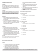
GENERAL PRECAUTIONS DANGER Risk of child entrapment, before you throw away your old refrigerator or freezer, take off the doors and leave shelves in place so that children may not easily climb inside. DANGER Altering, cutting of the power cord, or removal of the power cord, removal of power plug, or direct wiring can cause serious injury, fire and/or loss of property and/or life and will void the warranty.
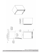
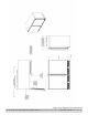
Figure 1. 24” Signature Series Dimensions 6 © 2011 24”, 48” & 72” Cabinet Installation / Operation Manual Document No.
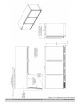
Figure 2. 48” Signature Series Dimensions © 2011 24”, 48” & 72” Cabinet Installation / Operation Manual Document No.
Figure 3. 72” Signature Series Dimensions 8 © 2011 24”, 48” & 72” Cabinet Installation / Operation Manual Document No.
PREPARING THE SPACE Make sure that the opening where the Perlick cabinet(s) is/are to be installed is properly prepared. Refer to Figure 1, 2 and 3 to ensure the space dimensions and electrical service are correct for the models to be installed. CAUTION If cabinet is being installed under a counter top it is recommended that the counter top be supported by structure other than the refrigerated cabinet to prevent damage to the counter top.
ANTI-TIP BRACKETS WARNING Unit may tip forward if loaded racks/shelves are all pulled out at the same time. To prevent tipping and provide a stable installation, the unit must be secured in place with the anti-tip brackets provided with the unit. A set of metal anti-tip brackets are supplied with the unit. The anti-tip brackets, when properly installed should secure the rear legs and prevent the unit from tipping forward.
Figure 5. TWO-DOOR ANTI-TIP LAYOUT Figure 6. THREE-DOOR ANTI-TIP LAYOUT © 2011 24”, 48” & 72” Cabinet Installation / Operation Manual Document No.
INSTALLATION IMPORTANT NOTE: If installing on a concrete floor, concrete fasteners are required and not included with the anti-tip kit. CAUTION Any finished flooring should be protected with appropriate material to avoid damage from moving the unit. If unit has been laid on its back or sides, place unit upright and allow minimum of 24 hours before connecting power.
TOE PLATE INSTALLATION When the unit is secured in place, install the louvered toe plate. Secure louvered toe plate by snapping the latch into the latch catch on the unit. Refer to Figure 7 TOE-PLATE INSTALLATION ILLUSTRATION CAUTION The louvered toe plate must be removable for servicing. The floor cannot interfere with removal. The louvered sections of the toe plate must not be covered or obstructed so as to prevent proper air circulation. Figure 7. TOE PLATE INSTALLATION.
DOOR OPTIONS HANDLE INSTALLATION Perlick units offer a variety of door panel design alternatives; solid stainless steel, solid wood overlay, stainless steel glass, wood overlay glass, solid stainless steel drawers and solid wood overlay drawers. This, together with door swing choices, result in a variety of possible combinations. CAUTION: Handle mounting on wood overlay door should be mounted on overlay panel only (not the door) to avoid damage to the factory door.
PROCEDURE FOR SWITCHING DIRECTION OF DOOR SWING ON PERLICK C-SERIES, 15 INCH, AND SIGNATURE SERIES CABINETS NOTE: Changing the door mount is not advisable if you have a door with custom wood overlay. doing so may result in having a handle that is in an undesirable position.
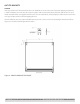
WOOD OVERLAY INSTALLATION Before beginning installation, check all components for proper fit and finish. WARNING • All overlay doors require a trim panel at least ¾” thick. • The solid wood overlay panel should not weigh more than 20 pounds. • The glass wood overlay panel should not weigh more than 10 pounds. The following instructions cover installing a solid wood overlay or glass overlay panel and handle to a door or drawer. IMPORTANT NOTE: Contact the factory or visit www.perlick.
Figure 8. SOLID WOOD OVERLAY PANEL © 2011 24”, 48” & 72” Cabinet Installation / Operation Manual Document No.
Figure 8-A. LOCK INSTALLATION -SOLID WOOD OVERLAY PANEL 18 © 2011 24”, 48” & 72” Cabinet Installation / Operation Manual Document No.
Figure 9. WOOD OVERLAY, GLASS DOOR PANEL © 2011 24”, 48” & 72” Cabinet Installation / Operation Manual Document No.
Figure 9-A. LOCK INSTALLATION -WOOD OVERLAY, GLASS DOOR PANEL 20 © 2011 24”, 48” & 72” Cabinet Installation / Operation Manual Document No.
Figure 10. SOLID WOOD OVERLAY DRAWERS © 2011 24”, 48” & 72” Cabinet Installation / Operation Manual Document No.
Figure 10-A. LOCK INSTALLATION -SOLID WOOD OVERLAY DRAWERS 22 © 2011 24”, 48” & 72” Cabinet Installation / Operation Manual Document No.
SHELVING IMPORTANT NOTE: Interior louver openings and fan guard openings should never be obstructed to achieve maximum performance. IMPORTANT NOTE: All shelving is inter-changeable with all products. Full-extension Shelving - Pull the shelf out to its farthest point. Locate the tabs in the middle on both sides of the extenders. Press left tab up and right tab down; pull shelf out. Move each extender separately.
vinyl coated wine racks capable of storing 88 total wine bottles. If the cabinet is a multi-zone wine reserve the first door can hold 40 total wine bottles while the second door can hold 48 total wine bottles. THREE DOOR ALL-REFRIGERATOR The three-door all-refrigerator (HP72ROO) comes standard with six black vinyl coated pullout shelves.
The unfinished faces should be finished and sealed. In many cases stains and/or finishes have odors that may be objectionable in an enclosed area. To remove the front wood-face from the wine shelf, simply pull out the wine shelf and remove the fasteners, finish as desired and re-install with fasteners. OPERATION 24” SIGNATURE SERIES Perlick’s 24” Signature Series units comes equipped with a state of the art refrigeration system.
Loading Product Interior Light IMPORTANT NOTE: Before storing perishables, allow unit to run for a minimum of 24 hours to allow temperature stabilization after start-up. The 72” unit has three interior lights that are illuminated when the corresponding door is opened. The unit also comes standard with manual light switches located next to each light for displaying your products through a glass door.
TEMPERATURE CONTROLLER © 2011 24”, 48” & 72” Cabinet Installation / Operation Manual Document No.
© 2011 24”, 48” & 72” Cabinet Installation / Operation Manual Document No.
IMPORTANT NOTE: Dependent on the model and configuration, the controllers have been programmed to only allow a temperature adjustment within a specified range (see chart below for the specified range allowed for your cabinet). © 2011 24”, 48” & 72” Cabinet Installation / Operation Manual Document No.
CHART 1. PRODUCT TEMPERATURE SET POINTS AND RANGES.
MAINTENANCE IMPORTANT NOTE: All multi-zone models must have a minimum of 8 degrees difference between zones CHECKING PRODUCT TEMPERATURE To accurately check the temperature of the product stored in a refrigerated compartment, insert an accurate thermometer into a plastic (non-breakable) bottle, partially filled with water. Tighten the bottle cap securely. Place the bottle in the desired area for 24 hours. Refrain from opening the unit during the testing period.
TROUBLESHOOTING BEFORE CALLING FOR SERVICE If the unit appears to be malfunctioning, read through NORMAL OPERATION first. If the problem persists, check the TROUBLESHOOTING GUIDE. Locate the problem in the guide and refer to the cause and its remedy before calling for service. The problem could be something, which can be solved without a service call.
Controller display is flashing “EE” • The controller has a data or memory failure The refrigerated cabinet isn’t running • Is there electrical power to the unit? • Is your home circuit breaker or fuse on? • Is your ON/OFF key pad on? • Is your condenser area clean? The refrigerated compartment is warmer than usual • Is your control set properly? • Is the light staying on? • Is your condenser area clean and free of obstructions? • Has the door been open for a long time or more frequent door openings occurred
Customer Service Department, 8300 W. Good Hope Rd, Milwaukee, WI 53223, call 800/558-5592 or e-mail us at warrantyserv@perlick.com. You need replacement parts or accessories • Use only genuine Perlick replacement parts and accessories. Genuine Perlick parts and accessories are designed to work correctly with Perlick products and offer superior service life.
your Perlick dealer, distributor or Perlick Corporation’s Technical Service Department; 8300 West Good Hope Road, Milwaukee Wisconsin, 53223; call 800 558-5592, E-mail us at warrantyserv@perlick.com, or visit our Web site: www.perlick.
© 2011 24”, 48” & 72” Cabinet Installation / Operation Manual Document No.
8300 W. Good Hope Road • Milwaukee, WI 53223 • 1-800-558-5592 • Fax: 414-353-7069 • www.perlick.com Perlick is committed to continuous improvement. Therefore, we reserve the right to change specifications without warning. © 2011 24”, 48” & 72” Cabinet Installation / Operation Manual Document No.