
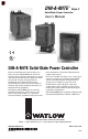
User`s manual


2
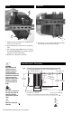
WATLOW DIN-A-MITE Style C User's Manual
General Specifications (2365)
Operator Interface
• Command signal input and indication light
• Alarm output and indication light
• Current limit indication LED
Amperage Rating
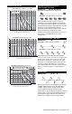
See the output rating curve chart on page 5 for all
the natural convection, fan-cooled, and through-
wall mount models.
Ratings are into a resistive heater load
• Maximum surge current for 16.6 milliseconds, 1,350 A
peak
• Maximum I
2
t for fusing is 9100 A
2
s
• Latching current: 500 mA minimum
• Holding current: 200 mA minimum
• Fan current: 0.14 A for 24 VÎ (dc); 0.12 A for 120 V~
(ac); 0.06 A for 240 V~ (ac)
• Off-state leakage 1 mA at 25°C (77°F) maximum
Line Voltage
• 24 to 48 V~ (ac) units: 20 V~ minimum to 53 V~
maximum
• 100 to 240 V~ (ac) units: 48 V~ minimum to 265 V~
maximum
• 277 to 600 V~ (ac) units: 85 V~ minimum to 660 V~
maximum
• 100 to 120 V~ (ac), 200 to 208 V~, 230 to 240 V~, 277
V~, 400 V~, 480 V~, 600 V~, -15%/+10%, 50 or 60
Hz independent +/-5% (Input Control Signal Type L, P
and S)
Alarms (zero cross models only)
Shorted SCR Alarm Option
• Alarm state when the input command signal is off and
a 10 A or more load current is detected by the current
transformer (two turns required for 5 A or three turns
for 2.5 A).
Open Heater Alarm Option
• Alarm state when the input command signal is on and
the load current detected by the current transformer is
less than the alarm set point. Available with Input
Control Signal option S only.
Alarm Output
• Energizes on alarm, non-latching
• Triac 24 to 240 V~ (ac), external supply with a current
rating of 300 mA @ 25°C (77°F), 200 mA @ 50°C
(122°F), 100 mA @ 80°C (176°F) and a holding current
of 200 µA with a latching current of 5 mA typical.
• Agency Approvals
• CE with proper filter:
89/336/EEC Electromagnetic Compatibility Directive
EN 61326: Industrial Immunity Class A emissions
Not suitable for Class B environments.
73/23/EEC Low Voltage Directive
EN 50178 Safety Requirements
Installation category III, Pollution degree 2
Phase angle and phase angle with current limit Input
Control Signal Types (P and L) are not CE approved.
•UL
®
50 Type 4X Enclosure and UL
®
1604 File E184390
(Through-wall heatsink mounting only)
•UL
®
508 listed and C-UL
®
, File E73741
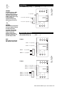
Input Terminals
• Compression: Will accept 0.2 to 2 mm
2
(24 to 14
AWG) wire
• Torque to 0.5 Nm (4.4 in-lb) with a 3.5 mm (1/8 in)
blade screwdriver
• Wire strip length 5.5 mm (0.22 in)
Line, Load and Ground Terminals
• Compression: Will accept 2 to 21 mm
2
(14 to 4 AWG)
wire
• Torque to 2.7 Nm (24 in-lb) with a 6.4 mm (1/4 in)
blade screwdriver, or a No. 2 Phillips screwdriver
• Wire strip length 11 mm (7/16 in)
Operating Environment
• See the output rating curve chart on page 5.
•0 to 90% RH (relative humidity), non-condensing
• Storage temperature: -40 to +85°C (-40 to 185°F)
• Insulation only tested to 3,000 meters
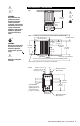
DIN Rail Mount
• DIN EN 50022, 35 mm by 7.5 mm
• Minimum clipping distance: 34.8 mm (1.37 in)
• Maximum clipping distance: 35.3 mm (1.39 in)
Back Panel Mount
• Four mounting holes M3 to M4 (No. 6 to No. 8)
fastener
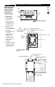
Through-Wall Mount
• See page 8 for through-wall cutout
Weight
• 1.0 to 1.9 kg (2.2 to 4.2 lb) depending upon model
Specifications are subject to change without notice.
LISTED
CUS