WATLOW ANAFAZE 8 PID CONTROLLER Installation And Operation Manual Revision 5 March 26, 1987 ANAFAZE 8 PID Serial Numbers P2000 and higher Watlow Anafaze 344 Westridge DR Watsonville, CA 95076 Phone: 831-724-3800 Fax: 831-724-0320 Copyright (c) 1987-1988.
STATEMENT OF WARRANTY ANAFAZE, Incorporated warrants that the Products furnished under this Agreement will be free from material defects in material and workmanship for a period of 90 days from the date of shipment. The customer shall provide notice to ANAFAZE, Incorporated of any such defect within one week after the Customer's discovery of such defect.
WARNING ANAFAZE HAS MADE EFFORTS TO ENSURE THE RELIABILITY AND SAFETY OF THE ANAFAZE 8 PID CONTROLLER AND PROVIDE RECOMMENDATIONS FOR ITS SAFE USE IN SYSTEMS APPLICATIONS. PLEASE NOTE THAT IN ANY APPLICATION, FAILURES CAN OCCUR THAT WILL RESULT IN FULL CONTROL OUTPUTS OR OTHER OUTPUTS THAT MAY CAUSE DAMAGE OR UNSAFE CONDITIONS IN THE EQUIPMENT OR PROCESS CONNECTED TO THE ANAFAZE 8 PID.
TABLE OF CONTENTS 1.0 INTRODUCTION ___________________________________________________1 2.0 SPECIFICATIONS __________________________________________________2 2.1 ANALOG INPUTS _________________________________________________2 2.2 OPERATING PARAMETERS _______________________________________2 2.3 REPORTING PARAMETERS _______________________________________3 2.4 COMMUNICATIONS ______________________________________________3 2.5 CONTROL AND ALARM OUTPUTS ________________________________3 2.
.0 CONTROL OUTPUTS ______________________________________________19 5.1 TIME PROPORTIONING VOLTAGE_______________________________19 5.2 ON/OFF VOLTAGE ______________________________________________20 5.3 ANALOG OUTPUT -- VOLTAGE OR CURRENT_____________________20 5.4 ISOLATED ANALOG OUTPUT -- VOLTAGE OR CURRENT __________20 5.5 DIGITAL INPUT _________________________________________________20 5.6 DIGITAL OUTPUTS ______________________________________________20 5.
1.0 INTRODUCTION The ANAFAZE 8 PID is a full-featured, industrial-quality, eight- loop, three-mode controller offering unique shared processing technology in local or distributed systems. Through shared processing, the operational functions are divided: the ANAFAZE 8 PID microprocessor intelligence controls the eight loops while a computer or programmable controller enters control settings and performs other operations as needed.
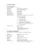
2.0 SPECIFICATIONS 2.1 ANALOG INPUTS Number of channels: Multiplexing: A/D converter: Loop update: Input isolation: Input resolution: Temp. coefficient: Measurement accuracy: Thermocouple break: Standard input types: Optional input types: eight three wire reed relay, guarded inputs integrating voltage to frequency each loop 2 times per second optical coupling 0.02% full scale .025% per degree +0.
2.3 REPORTING PARAMETERS The computer can request any of the following for any loop: Operating parameters: Analog inputs: all of the above sensor input 2.4 COMMUNICATIONS Types Baud rate Error check Isolation Data format Display RS-232, RS-422, or 20ma current loop jumper selectable, 300 to 9600 full echo of all settings optical for 20ma, optional for RS-232 standard ASCII LED indicates communication active 2.
2.8 SUBASSEMBLY IDENTIFICATION The ANAFAZE 8 PID controller consists of a measurement/processing unit with integral mounting frame, plug-in terminals for field wiring, LED indicators, power supply, and 9 card slots.
3.0 INSTALLATION There are some precautions that must be observed when installing the ANAFAZE 8 PID: WARNING-ELECTRICAL SHOCK DANGER It is very important that all signal lines including the power input be disconnected before servicing the ANAFAZE 8 PID. HIGH VOLTAGE MAY BE PRESENT EVEN WHEN POWER IS TURNED OFF.
6
For optimum performance when directly connecting thermocouple inputs, the terminal strips should be kept horizontal. In addition the unit should be protected from thermal shocks whenever possible. This will minimize any temperature gradients across the terminal strips and result in the highest accuracy. 3.1.2 ENCLOSURES Different enclosures can be used depending on the environmental protection required. 3.1.
Please note that the ANAFAZE 8 PID does not require an automatic LF line feed at the end of each communication. Do not use this feature available in the IBM PC BASIC or any other software package. 3.2.2 COMMUNICATIONS PLUG IN OPTIONS Communication interfaces plug into slot 1 at the back of the ANAFAZE 8 PID frame. The standard selection includes: RS- 232, RS-422, and 20ma current loop. An optically isolated RS-232 interface is available. 3.2.
If the host computer uses RTS and CTS or DSR and DTR, these lines should be connected together in pairs [or as shown in the computer manual]. Normally this is done in the RS-232 connector hood at the host computer. Alternately the effect of these lines can be eliminated in software. The ANAFAZE 8 PID is ready to receive data; therefore these lines are not required. 3.2.
The connections are shown for a single controller: Multiple ANAFAZE 8 PIDs' are connected in series. R+ is connected to the first unit TXD and TXD* from the first unit is connected to TXD of the next unit. These serial connections are continued until the last unit is reached. The last unit TXD* is connected to the computer R-. T+ is connected to the first unit RXD and the RXD* is connected to the next unit. The last unit RXD* is connected to the computer T- as shown: 3.2.
Multiple ANAFAZE 8 PID's are connected in parallel. The RXD of the first unit is connected to the RXD of the next unit, the RXD* to the RXD*, and the TXD* to the TXD*. 3.3 CONFIGURATION 3.3.1 CONFIGURATION SWITCH WARNING - TURN OFF POWER BEFORE CHANGING SWITCH The unit configuration switch is located near the center of the main circuit board. It is a six position DIP switch which is used to set the unit number.
3.3.2 BAUD RATE SELECTION WARNING - TURN OFF POWER BEFORE CHANGING BAUD RATE Baud rate is selected by positioning a selector jumper on J1 on the main circuit board. The position farthest from the card cage is 600 baud and the positions are then as follows: 600 300 2400 4800 1200 9600 Units are normally shipped from the factory with the baud rate set at 2400 baud. This rate is recommended for most applications. 3.
4.0 ANALOG INPUTS Connecting analog signals to the ANAFAZE 8 PID is normally straightforward. Most signals, including thermocouples can be directly connected and mixed in any order. However, some problems may occur that could reduce accuracy and possibly damage the unit. Sections 4.1 through 4.4 indicate some of the potential areas for concern. [See typical input DIAGRAM in section 4.13] 4.
4.5 USE OF THE SHIELD CONNECTION The shield connection provides a third input which is switched as each channel is measured. It is the ground reference for the measurement section. By switching this reference with every channel, the effective measurement ground can float to match the ground at the sensor, thus greatly reducing the error caused by different ground potentials (common mode). The system is factory set for use with non-shielded cables. Jumper JU1 connects all low inputs to shield.
RA, RB, RC, and RD are selected separately for each input and are labeled on the PC board for each loop. CH 1 (channel 1) is loop 1 etc. Resistors should be 1% metal film, 1/4 watt or better for higher accuracy. Other components such as capacitors can also be installed when required for signal conditioning. Please consult ANAFAZE. The resistors are normally soldered on the component side of the main PC board before installation. The silk screen shows the location of each input.
4.9 CURRENT TRANSMITTER INPUTS Current inputs are accommodated by placing resistors in the input section to convert the current input into a voltage. Different current input ranges are accommodated by selecting the proper resistor values. In general RC is selected to maintain a low source resistance. RA and RC produce the input full scale of 60mv. The positive input should be connected to the AUX terminal, and the negative input to the LOW terminal.
4.11 SCALING AND CALIBRATION Since a computer is used to display the reading and load the setpoints, a mathematical step can be used to convert measurements and setpoints to engineering units and correct for known sensor calibration errors. For example, the ANAFAZE 8 PID does all thermocouple calculations in degrees F since this provides almost twice the resolution of degrees C.
4.
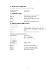
5.0 CONTROL OUTPUTS Control output boards are plugged into rear slots on the main circuit board as follows: ANAFAZE 8 PID serial numbers above 2000 only. Loop 1 2 3 4 5 6 7 8 Slot OUT 1 OUT 2 OUT 3 OUT 4 OUT 5 OUT 6 OUT 7 OUT 8 Comm COMM (communications interface) Note: Use caution when inserting or removing boards. Power must be off and care must be taken to align the pins and insert the boards without bending the pins.
The time proportioning output is turned on for a percentage of the ANAFAZE 8 PID cycle time according to the calculated control output. Thus if the calculation calls for 20% output and the cycle time is 5 seconds the output will be on for 1 second and then off for 4 seconds. 5.2 ON/OFF VOLTAGE The on/off voltage board provides the same voltage output as the time proportioning voltage board except the cycle time is not used.
Output 1 pin is labeled "AL 1". Output 2 pin is labeled "AL 2".
1. As a TTL signal by connecting to "AL" pin and "GND". ON < 0.5V at 4ma sink OFF = 5V at 400ohm source resistance 2. To drive A 3-32V type solid state relay. TRUE LOGIC Connect "AL" pin to - side of control input. Connect +5V (pin "SP7" for S.N.P2000 and above) to + side of control input. When output is on, relay turns on. When output is off, relay turns off. 3. To drive a 3-32V type solid sate relay. INVERTED LOGIC Connect "AL" pin to + side of relay. Connect "GND" pin to - side of relay.
6.0 OPERATION The ANAFAZE 8 PID is operated using the communications interface according to the commands sent from the host computer. ANAFAZE provides a standard software package for IBM and compatible computers -- ANASOFT-PID. Alternatively a custom program can be written according to the guidelines in 6.2 6.1 ANASOFT-PID ANASOFT-PID is a menu driven program that operates up to 16 ANAFAZE 8 PID controllers using an IBM PC or compatible computer.
The host computer manual provides the information needed to write this type of program. An example in BASIC is provided in Appendix 1 for the IBM PC. An alternative method for system checkout is to use a terminal to verify correct operation of the ANAFAZE 8 PID and the interface cable. 6.4 MANUAL OPERATION WITH HOST COMPUTER After the software, as described in section 6.3, is written the host computer is connected to the ANAFAZE 8 PID as described in section 3.
7.0 COMMAND STRUCTURE Communication between the ANAFAZE 8 PID and the host computer is accomplished with ASCII code. The baud rate can be selected from 300 to 9600 baud. Please see the hardware section of the manual for baud rate selection and interface description. The following ASCII formats are used: 1. ASCII CAPITAL letters are always used. 2. All commands and responses are terminated with an ASCII carriage return (CR). 3.
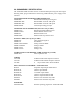
Standard Input Types: Code Input J J thermocouple -50 to 1400 F K K thermocouple -110 to 2500 F T T thermocouple -120 to 750 F U 0 to 100%, 0 to 60mv See hardware sections for scaling milliamp and voltage inputs when using the U range. Setpoints for millivolt inputs are in percent of full scale to the nearest 0.1% i.e., values from 0000 to 1000. Setpoints for thermocouple inputs are in degrees F to the nearest degree.
Command: K5PQRC Response: K5P200CRLF loop 5 proportional gain is 200 To set the integral multiplier: T(1)M(a)CR T is the time indicator 1 affects all loops M indicates the multiplier a is the value from 1 to 3 Command affects all loops. The integral multiplier sets the range and resolution of the integration time.
To pre-set the integral sum value: I(n)S(abcde)CR I is the Integral indicator n is the loop number 1 to 8 S is integral sum indicator abcde is the value from 0 to 65536 Normally this is set to 0 when control is first started. Although the integral sum can be negative in the calculation it can only be preset positive.
Digital Filter 0 1 2 3 4 5 6 7 8 9 10 11 12 13 14 15 ASCII character 0 1 2 3 4 5 6 7 8 9 : ; < = > ? Example: Command: D3F4CR sets digital filter level 4 for loop 3 Response: D3F4CRLF To query for the digital filter value: D(n)QCR 7.4 ANALOG (CONTROL) OUTPUT To set the analog output and suspend PID control: O(n)V(abcd)CRO is the output indicator n is the loop number V is suspend control indicator abcd is the value 0 to 1023.
Example: Command: O7V0512CR suspends control and sets output to 50% Response:O7V0512CRLF control is suspended, output fixed at 50% To initiate PID control: O(n)P0000CR O is the output indicator n is the loop number P is the start control indicator 0000 is a filler in the command Example: Command: O5P0000CR turn on PID control for loop 5 Response: O5P0213CRLF control is on for loop 5 output value is 213 out of 1024 or 20.8% full scale.
Example: Command: T1R00090CR sets cycle time to about 5 seconds Response: TR00090CRLF cycle time is about 5 seconds To query the cycle time: T1RQCR 7.
Example: Command: S3CR read analog input loop 3 (J/TC) Response: S3+11867CRLF temperature loop 3 is 1186.7 F Example: Command: S6CR read analog input loop 6 (millivolt) Response: S6+08765CRLF input is 87.
Example: Command: SFCR Response: +032;+001;+0334+0333+033=+034>+61:8+31:?CRLF the value for loop 8 is calculated from 31:? 3*4096 + 1*256 + 10*16 + 15 =12719 As loop 8 is a J/TC this is 1271.
APPENDIX 1 - SAMPLE BASIC TERMINAL PROGRAM FOR IBM PC This program will transmit characters entered on the keyboard to the ANAFAZE 8 PID and display them on the screen. Characters sent from the ANAFAZE 8 PID will also be displayed. The program is set for 2400 baud -- which is how the ANAFAZE 8 PID's are configured when they are shipped from the factory.
ANAFAZE 8 PID AEX (ALARM EXPANDER BOARD) OPTION MANUAL SUPPLEMENT Revision 2 March 26, 1987 Watlow Anafaze 344 Westridge DR Watsonville, CA 95076 Phone: 831-724-3800 Fax: 831-724-0320 Copyright (c) 1987. All RIGHTS RESERVED: No part of this publication may be reproduced, stored in a retrieval system or transmitted in any form by any means; electronic, mechanical, photo copying, recording, or otherwise, without the prior written permission of Watlow Anafaze Printed in U.S.A.
ANAFAZE 8 PID AEX (ALARM EXPANDER BOARD) OPTION ANAFAZE 8 PID MANUAL SUPPLEMENT CONTENTS 1. THEORY OF OPERATION _____________________________________ 1 1.1 AUTOMATIC ALARM MODE ______________________________________1 1.2 I/O CONTROL MODE _____________________________________________3 2. HARDWARE DESCRIPTION ___________________________________ 4 2.1 ANAFAZE 8-PID CONNECTION ____________________________________4 2.2 EXTERNAL INTERFACE __________________________________________4 2.
1. THEORY OF OPERATION The Alarm Expander Module (AEX) is an optional plug-in card for the ANAFAZE 8 PID that provides 22 discrete input/output lines and EEROM [memory] storage capability for PID loop constants and output states. Of the 22 I/O lines, six are dedicated as inputs while the remaining 16 are userselectable as inputs or outputs in groups of four. A combination of hardware jumpers and software direction commands is used to dictate data direction.
1.1.1 ALARM MODE I/O LINE CONFIGURATION The alarm mode input and output designations are as follows: I/O Line Nr.
The user may select an alarm deadband of 0 to 9 % of the setpoint. Refer to the command summary at the end of this section for further information. Entering a deviation percentage of 0% (which is the default value) will result in no deadband and alarms will be set and cleared as measured temperatures cross the alarm setpoints. NOTE: Entering a new deviation percentage will result in the 8 upper and 8 lower deadband limits being recalculated instantly.
2. HARDWARE DESCRIPTION 2.1 ANAFAZE 8-PID CONNECTION The Alarm Expander Board plugs into the A8PID at connector J3 and connects to J2 by a short ribbon cable. The alarm expander can be used with ANAFAZE 8 PID units with a serial number of 2000 and higher. Please consult the factory for information regarding earlier units. 2.2 EXTERNAL INTERFACE The I/O interface is accomplished by a 50-pin flat cable connecting J1 on the AEX Board to an external I/O Module Board such as the GORDOS PB-24 or OPTO PB-24.
2.2.1 CONNECTOR TYPES REQUIRED The Alarm Expander Board is designed to interface directly to the PB24 Board with a 50 pin ribbon cable (optional...ANAFAZE P/N P2000). If the user wishes to provide his own cable, use a 50 pin socket connector, Spectra-Strip 802-050-002 or equivalent. 2.2.2 INTERFACE CHARACTERISTICS The Alarm Expander interface circuitry is designed to interface to optical isolators to avoid problems caused by noise in an industrial environment.
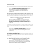
Refer to the diagram below for interconnection and jumper information: EXPANDER BOARD _o | J7 GND _o | J6 GND _o | J5 GND _o | J4 GND ____ J1 PIN | |----- 47 | U5 |----- 45 | |----- 43 |____|----- 41 | | o_|_|______+5V ____ | |----- 39 | U4 |----- 37 | |----- 35 |____|----- 33 | | o_|_|______+5V ____ | |----- 31 | U3 |----- 29 | |----- 27 |____|----- 25 | | o_|_|______+5V ____ | |----- 23 | U2 |----- 21 | |----- 19 |____|----- 17 | | o_|_|______+5V __________ I/O LINE NR ------| |--------- 00 ------|
3. COMMAND SUMMARY All AEX commands are prefaced by the character 'X' to identify it as an "eXpander" card command. I/O lines are addressed from 00 to 21 to correspond with I/O Module Board designations. When writing to all outputs with a single command (See Section 3.8) a bit position is reserved for all 22 lines regardless of whether they are inputs or outputs. The unnecessary bits will not affect the status of input lines. 3.
Examples: Channel Input Type Thermocouple 0050 Millivolt Range 0050 Setpoint Entered 50 Degrees F 5.0% Full Scale Interpretation NOTE: No internal check is made to confirm that the setpoint entered is valid within the channel input TYPE operating range. It is the users responsibility to insure that valid setpoints are entered with respect to the channel type designated.
Example: Command: X2LQ Response: X2L0100 Setting any alarm value updates both the run-time (RAM) and stored (ROM) data. On power-up the alarm values will be read from EEROM storage and will default to their last entered value. 3.3. SAVING PARAMETERS TO EEROM STORAGE The user may instruct the ANAFAZE 8 PID to save all current parameters in EEROM for use as default values on next power-up or microprocessor reset.
3.4 DEFINING I/O LINES AS INPUTS OR OUTPUTS (CONTROL MODE ONLY) If Control Mode is selected the user may define the four groups of I/O lines as input or output for each group. XD (abcd) D is the Direction indicator a, b, c and d are either 0 or 1 indicating whether group 1, 2, 3 and 4, respectively, are inputs (0) or outputs (1). Example: Command: XD0011 Sets group 1 and 2 (lines 0-7)as input and group 3 and 4 (lines 8-15) as outputs.
Or: XS03O Input 3 is ON (HIGH level TTL signal) 3.6 SETTING INDIVIDUAL OUTPUT LINE LEVELS I/O lines defined as Outputs may be set or cleared individually. Lines must be addressed by their two digit I/O Line Nr (00-15). It is the users responsibility to properly address lines designated as outputs although attempting to set or clear an input line will have no affect on that line. XO (n)(a) O is the Output indicator n is the output line nr.
3.8 WRITING ALL OUTPUT LINES All 16 possible output Lines may be set or cleared simultaneously with one command. The desired level of each line [1=High(ON) 0=Low(OFF)] is represented by one bit in a hexadecimal byte representing each four-line group. Refer to Section 3.10 for further explanation of this compressed data format.
3.9 SETTING THE ALARM DEADBAND where a is the percentage (0-9) XAD(a) Example: Command : XAD1 Select a 1% deadband Response: XAD1 Example: Loop 3 (J T/C) High Alarm Set - 1000 F Low Alarm Set - 900 F Deadband Percent - 1 % High Alarm will clear at 990 F Low Alarm will clear at 909 F Example: Loop 8 (Millivolt) High Alarm Set - 0900 (90% FS) Low Alarm Set - 0100 (10% FS) Deadband Percent- 1 % High Alarm will clear at 89.1% FS Low Alarm will clear at 10.1% FS 3.
The ASCII characters are derived as per the following table: Value 00 01 02 03 04 05 06 07 08 09 10 11 12 13 14 15 Hex Value Binary Value ASCII Character 0 1 2 3 4 5 6 7 8 9 A B C D E F 0000 0001 0010 0011 0100 0101 0110 0111 1000 1001 1010 1011 1100 1101 1110 1111 0 1 2 3 4 5 6 7 8 9 : ; < = > ? ASCII (Hex) 30 31 32 33 34 35 36 37 38 39 3A 3B 3C 3D 3E 3F Code (Decimal) 48 49 50 51 52 53 54 55 56 57 58 59 60 61 62 63 Examples: I/O Line Nrs - Groups LINE # 6 ----21 20 5 ----------19 18 17 16 Wri