EZ-ZONE PM ® User’s Guide Integrated Controller Models TOTAL CUSTOMER SATISFACTION 3 Year Warranty ISO 9001 1241 Bundy Boulevard., Winona, Minnesota USA 55987 Phone: +1 (507) 454-5300, Fax: +1 (507) 452-4507 http://www.watlow.com 0600-0059-0000 Rev. M April 2013 Registered Company Winona, Minnesota USA Made in the U.S.A.
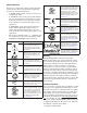
Safety Information Unit is a Listed device per Underwriters Laboratories®. It has been evaluated to United States and Canadian requirements for Hazardous Locations Class 1 Division II Groups A, B, C and D. ANSI/ISA 12.12.01-2007. File E184390 QUZW, QUZW7. See: www.ul.com We use note, caution and warning symbols throughout this book to draw your attention to important operational and safety information. A “NOTE” marks a short message to alert you to an important detail.
• All configuration information • User's Guide • Factory Page Return Material Authorization (RMA) 1. Call Watlow Customer Service, (507) 454-5300, for a Return Material Authorization (RMA) number before returning any item for repair. If you do not know why the product failed, contact an Application Engineer or Product Manager. All RMA’s require: • Ship-to address • Bill-to address • Contact name • Phone number • Method of return shipment • Your P.O.
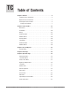
TC Table of Contents Chapter 1: Overview . . . . . . . . . . . . . . . . . . . . . . . . . . . . . . . . . . . . . 4 Standard Features and Benefits . . . . . . . . . . . . . . . . . . . . . . . . . . . . . . . . 4 Optional Features and Benefits. . . . . . . . . . . . . . . . . . . . . . . . . . . . . . . . . 5 A Conceptual View of the PM. . . . . . . . . . . . . . . . . . . . . . . . .
TC Table of Contents (cont.) Chapter 6: Setup Page. . . . . . . . . . . . . . . . . . . . . . . . . . . . . . . . . . . 67 Analog Input Menu. . . . . . . . . . . . . . . . . . . . . . . . . . . . . . . . . . . . . . . . . 69 Linearization Menu. . . . . . . . . . . . . . . . . . . . . . . . . . . . . . . . . . . . . . . . . 71 Process Value Menu. . . . . . . . . . . . . . . . .
TC Table of Contents (cont.) Current Sensing. . . . . . . . . . . . . . . . . . . . . . . . . . . . . . . . . . . . . . . . . . 138 Open Loop Detection . . . . . . . . . . . . . . . . . . . . . . . . . . . . . . . . . . . . . . 138 Programming the EZ Key/s. . . . . . . . . . . . . . . . . . . . . . . . . . . . . . . . . . 138 Using Lockout and Password Security. . . . . . . . . . . . .
1 Chapter 1: Overview The EZ-ZONE ® PM takes the pain out of solving your thermal loop requirements. Watlow’s EZ-ZONE PM controllers offer options to reduce system complexity and the cost of control-loop ownership. You can order the EZ-ZONE PM as a PID controller or an over-under limit controller, or you can combine both functions in the PM Integrated Limit Controller.
Heat-Cool Operation • Provides application flexibility with accurate temperature and process control Optional Features and Benefits High-amperage Power Control Output • Drives 15 amp resistive loads directly • Reduces component count • Saves panel space and simplifies wiring • Reduces the cost of ownership Integrated PID and Limit Controller • Reduces wiring time and termination complexity compared to connecting discrete products • Decreases required panel space • Lowers installation costs • Increases user
A Conceptual View of the PM The flexibility of the PM’s software and hardware allows a large range of configurations. Acquiring a better understanding of the controller’s overall functionality and capabilities while at the same time planning out how the controller can be used will deliver maximum effectiveness in your application. It is useful to think of the controller in terms of functions; there are internal and external functions.
Getting Started Quickly The PM control has a page and menu structure that is listed below along with a brief description of its purpose. Setup Page Push and hold the up and down keys (¿ ¯) for 6 seconds to enter. (See the Setup Page for further information) Once received, a user would want to setup their control prior to operation. As an example, define the input type and set the output cycle time. Operations Page Push and hold the up and down keys (¿ ¯) for 3 seconds to enter.
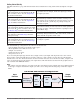
EZ-ZONE® PM Integrated Model 1/16 DIN System Diagram With a Current Transformer, Without Communications Card (Slot B) Input Functions Input Sensor - None - Idle set point - Tune - Alarm clear, request - Force alarm - Silence alarm - Manual/auto mode - Control outputs off - Remote set point enable - Lock keypad - TRU-TUNE+® disable - Loop & alarms off - Profile disable - Profile hold/resume - Profile start - Profile start/stop - Restore user settings - Event inputs RUI, EZ-ZONE Controllers, PLC, PC or HMI
EZ-ZONE® PM Integrated Model 1/16 DIN System Diagram With Auxillary Input, Without Communications Card (Slot B) Input Functions Input Sensor - None - Idle set point - Tune - Alarm clear, request - Force alarm - Silence alarm - Manual/auto mode - Control outputs off - Remote set point enable - Lock keypad - TRU-TUNE+® disable - Loop & alarms off - Profile disable - Profile hold/resume - Profile start - Profile start/stop - Restore user settings - Event inputs RUI, EZ-ZONE Controllers, PLC, PC or HMI PID C
EZ-ZONE® PM Integrated Model 1/16 DIN With Limit, System Diagram Without Communications Card (Slot B) Input Functions Input Sensor - None - Limit reset - Idle set point - Tune - Alarm clear, request - Force alarm - Silence alarm - Manual/auto mode - Control outputs off - Remote set point enable - Lock keypad - TRU-TUNE+® disable - Loop & alarms off - Profile disable - Profile hold/resume - Profile start - Profile start/stop - Restore user settings - Event inputs PID Controller Analog Input 1 none, Therm
EZ-ZONE® PM Integrated Model 1/16 DIN System Diagram with Expanded Communications (Slot B) Input Functions Input Sensor - None - Idle set point - Tune - Alarm clear, request - Force alarm - Silence alarm - Manual/auto mode - Control outputs off - Remote set point enable - Lock keypad - TRU-TUNE+® disable - Loop & alarms off - Profile disable - Profile hold/resume - Profile start - Profile start/stop - Restore user settings - Event inputs PID Controller Analog Input 1 none, CT, Thermocouple, RTD (100 Ω,
EZ-ZONE® PM Integrated Model 1/8 and 1/4 DIN System Diagram Without 6EZ-ZONE Digital I/O (slot D), Without PM Integrated 8th DINCommunications System Diagram (slot E) Input Function Input Sensor Without 6-digital I/O (slot D), Without Comms Card (slot E) Analog Input 1 none, Thermocouple, RTD (100Ω, 1kΩ), Thermistor 5kΩ, 10kΩ, 20kΩ, 40kΩ) Process (V, mV, mA) or 1k Potentiometer PID Controller (Optional Ramp/Soak max 4 files, 40 steps) Slots A (Optional) Input Sensor - None - Limit reset - Idle set p
EZ-ZONE® PM Integrated Model 1/8 and 1/4 DIN System Diagram EZ-ZONE 8th DIN System Diagram With 6 Digital I/O PM (slotIntegrated D), Without Communications (slot E) With 6-digital I/O (slot D), Without Comms Card (slot E) Input Function Input Sensor Analog Input 1 none, Thermocouple, RTD (100Ω, 1kΩ), Thermistor 5kΩ, 10kΩ, 20kΩ, 40kΩ) Process (V, mV, mA) or 1k Potentiometer PID Controller (Optional Ramp/Soak max 4 files, 40 steps) Slots A (Optional) Input Sensor Analog Input 2 none, CT, Thermocouple,
EZ-ZONE® PM Integrated Model 1/8 and 1/4 DIN with CT System Diagram EZ-ZONE PMI/O Integrated 8thWithout DIN withCommunications CT System Diagram Without 6 Digital (slot D), (slot E) Input Function Input Sensor Without 6-digital I/O (slot D), Without Comms Card (slot E) Analog Input 1 none, Thermocouple, RTD (100Ω, 1kΩ), Thermistor 5kΩ, 10kΩ, 20kΩ, 40kΩ) Process (V, mV, mA) or 1k Potentiometer PID Controller (Optional Ramp/Soak max 4 files, 40 steps) Slots A (Optional) Output Function Output 1 none,
EZ-ZONE® PM Integrated Model 1/8 and 1/4 DIN System Diagram WithoutEZ-ZONE 6 Digital PM I/O Integrated (slot D), With Communications 8th DIN System Diagram(slot E) Input Function Input Sensor Without 6-digital I/O (slot D), With Comms Card (slot E) Analog Input 1 none, Thermocouple, RTD (100Ω, 1kΩ), Thermistor 5kΩ, 10kΩ, 20kΩ, 40kΩ) Process (V, mV, mA) or 1k Potentiometer PID Controller (Optional Ramp/Soak max 4 files, 40 steps) Slots A (Optional) Input Sensor Analog Input 2 none, CT, Thermocouple,
2 Chapter 2: Install and Wire Dimensions 1/16 DIN (PM6) 15.8 mm (0.62 in) 101.6 mm (4.00 in) 53.3 mm (2.10 in) 53.3 mm (2.10 in) Side Front 51.2 mm (2.02 in) L1 L3 K1 K3 99 J1 J3 CF L2 L4 CD K2 98 K4 CE T1 T2 B5 S1 S2 D6 R1 R2 D5 Top Back 1/16 DIN (PM6) Recommended Panel Spacing 44.96 to 45.47 mm (1.77 to 1.79 inches) Recommended panel spacing 44.96 to 45.47 mm (1.77 to 1.79 inches) 21.6 mm (0.85 in) minimum panel thickness 1.53 to 9.52 mm (0.060 to 0.375) 21.6 mm (0.
1/8 DIN (PM8) Vertical Dimensions 15.75 mm (0.62 in) 1.52 mm (0.06 in) 53.34 mm (2.10 in) 100.33 mm (3.95 in) 54.8 mm (2.16 in) 10.16 mm (0.40 in) 30.73 mm (1.21 in) 101.60 mm (4.00 in) 1/8 DIN (PM8) Vertical Recommended Panel Spacing 44.96 to 45.60 mm (1.77 to 1.79 inches) 92.00 to 92.80 mm (3.62 to 3.65 inches) Panel thickness (0.060 in) 1.53 mm to (0.375 in) 9.52 mm 21.6 mm (0.85 in) Minimum 21.6 mm (0.
1/8 DIN (PM9) Horizontal Dimensions 15.75 mm (0.62 in) 1.52 mm (0.06 in) 100.33 mm (3.95 in) 53.8 mm (2.16 in) 53.34 mm (2.10 in) 10.16 mm (0.40 in) 30.73 mm (1.21 in) 101.60 mm (4.00 in) 1/8 DIN (PM9) Horizontal Recommended Panel Spacing 92.00 to 92.80 mm (3.62 to 3.65 inches) 44.96 to 45.60 mm (1.77 to 1.79 inches) Panel thickness (0.060 in) 1.53 mm to (0.375 in) 9.52 mm 21.6 mm (0.85 in) Minimum 21.6 mm (0.
1/4 DIN (PM4) Dimensions 15.75 mm (0.62 in) 1.52 mm (0.06 in) 100.33 mm (3.95 in) 100.33 mm (3.95 in) 12.70 mm (0.50 in) 30.73 mm (1.21 in) 100.84 mm (3.97 in) 1/4 DIN (PM4) Recommended Panel Spacing 92.0 to 93.0 mm (3.62 to 3.65 inches) 92.0 to 93.0 mm (3.62 to 3.65 inches) 21.6 mm (0.85 inches) Minimum Panel thickness 1.53 to 9.52 mm (0.060 to 0.375 inches) 21.6 mm (0.
Installation 1. Make the panel cutout using the mounting template dimensions in this chapter. Insert the case assembly into the panel cutout. 2. While pressing the case assembly firmly against the panel, slide the mounting collar over the back of the controller. If the installation does not require a NEMA 4X seal, simply slide together until the gasket is compressed. 3.
Removing the Mounted Controller from Its Case 1. From the controller's face, pull out the tabs on each side until you hear it click. Pull out the tab on each side until you hear it click. Grab the unit above and below the face and pull forward. 2. Grab the unit above and below the face with two hands and pull the unit out. On the PM4/8/9 controls slide a screwdriver under the pry tabs and turn. çWarning: • This equipment is suitable for use in class 1, div.
Wiring Slot A Slot B 1 2 T1 S1 T2 S2 R1 R2 Slot D Slot E Inputs Terminal Function S2 (RTD) or current + S3 (RTD), thermocouple -, current - or volts -, potentiometer wiper, thermistor S1 (RTD), thermocouple + or volts +, thermistor, potentiometer Universal / Thermistor Input input 1: all configurations input 2: PM _ _ _ _ _ - _ [R,L] _ _ _ _ _ mA ac mA ac Current Transformer PM _ _ _ _ _ - _ [T] _ _ _ _ _ B7 Common D7 digital input or output Digital Inputs PM[4,8,9] _ _ _ _ - [C, D] _ _ _
Communications Slot A Terminal Function CB CA CC CB CA C5 C3 C2 CB CA CC CB CA C5 C3 C2 Modbus Modbus Modbus Modbus Modbus Modbus Modbus Modbus V+ CH SH CL V- V+ CH SH CL V- DeviceNet™ power Positive side of DeviceNet™ bus Shield interconnect Negative side of DeviceNet™ bus DeviceNet™ power return DeviceNet™ Communications Slot B: PM6 _ _ _ _ - [5] A A A _ _ _ Slot E: PM[4,8,9] _ _ _ _ - [5] _ _ _ _ _ _ E8 E7 E6 E5 E4 E3 E2 E1 E8 E7 E6 E5 E4 E3 E2 E1 EtherNet/IP™ EtherNet/IP™ EtherNet/IP™ EtherN
Back View Slot Orientation 1/4 DIN Horizontal PM4 Input 2 Input 1 Output 3 Output 4 A C B Dig I/O 5 & 6 485 Comms Power Power Dig I/O 5 & 6 485 Comms Output 4 C Output 3 E Output 2 Input 1 D Output 1 Communications Card Output 2 Digital I/O 7 - 12 Output 1 A Back View Slot Orientation 1/16 DIN PM6 Input 2 Note: Slot B above can also be configured with a communications card.
Warning: Óç Use National Electric (NEC) or other country-specific standard wiring and safety practices when wiring and connecting this controller to a power source and to electrical sensors or peripheral devices. Failure to do so may result in damage to equipment and property, and/or injury or loss of life. Low Power Slot C Note: Adjacent terminals may be labeled differently, depending on the model number. Note: To prevent damage to the controller, do not connect wires to unused terminals.
Warning: Óç Use National Electric (NEC) or other country-specific standard wiring and safety practices when wiring and connecting this controller to a power source and to electrical sensors or peripheral devices. Failure to do so may result in damage to equipment and property, and/or injury or loss of life. Note: Maximum wire size termination and torque rating: • 0.0507 to 3.30 mm2 (30 to 12 AWG) single-wire termination or two 1.31 mm2 (16 AWG) • 0.8 Nm (7.0 lb.-in.
Warning: Óç Input 1, 2 Process Slot A, B Use National Electric (NEC) or other country-specific standard wiring and safety practices when wiring and connecting this controller to a power source and to electrical sensors or peripheral devices. Failure to do so may result in damage to equipment and property, and/or injury or loss of life. Maximum wire size termination and torque rating: • 0.0507 to 3.30 mm2 (30 to 12 AWG) single-wire termination or two 1.31 mm2 (16 AWG) • 0.8 Nm (7.0 lb.-in.
Warning: Óç Use National Electric (NEC) or other country-specific standard wiring and safety practices when wiring and connecting this controller to a power source and to electrical sensors or peripheral devices. Failure to do so may result in damage to equipment and property, and/or injury or loss of life.
Warning: Óç Use National Electric (NEC) or other country-specific standard wiring and safety practices when wiring and connecting this controller to a power source and to electrical sensors or peripheral devices. Failure to do so may result in damage to equipment and property, and/or injury or loss of life. Switched DC Wiring Example Using DO 5-6 switched dc outputs Htr 1 D5 VDC Htr 2 D6 Note: + + - B5 Maximum wire size termination and torque rating: • 0.0507 to 3.
Warning: Óç Use National Electric (NEC) or other country-specific standard wiring and safety practices when wiring and connecting this controller to a power source and to electrical sensors or peripheral devices. Failure to do so may result in damage to equipment and property, and/or injury or loss of life. Note: Maximum wire size termination and torque rating: • 0.0507 to 3.30 mm2 (30 to 12 AWG) single-wire termination or two 1.31 mm2 (16 AWG) • 0.8 Nm (7.0 lb.-in.
Warning: Óç Use National Electric (NEC) or other country-specific standard wiring and safety practices when wiring and connecting this controller to a power source and to electrical sensors or peripheral devices. Failure to do so may result in damage to equipment and property, and/or injury or loss of life. Output 1, 3 Switched DC/Open Collector Slot A, B common X_ dc - (open collector) W_ dc + Y_ Note: Maximum wire size termination and torque rating: • 0.0507 to 3.
Warning: Óç Use National Electric (NEC) or other country-specific standard wiring and safety practices when wiring and connecting this controller to a power source and to electrical sensors or peripheral devices. Failure to do so may result in damage to equipment and property, and/or injury or loss of life. Output 1, 3 Solid-State Relay, Form A Slot A, B • 0.
Warning: Óç Use National Electric (NEC) or other country-specific standard wiring and safety practices when wiring and connecting this controller to a power source and to electrical sensors or peripheral devices. Failure to do so may result in damage to equipment and property, and/or injury or loss of life.
Warning: Óç Use National Electric (NEC) or other country-specific standard wiring and safety practices when wiring and connecting this controller to a power source and to electrical sensors or peripheral devices. Failure to do so may result in damage to equipment and property, and/or injury or loss of life.
Warning: Óç Use National Electric (NEC) or other country-specific standard wiring and safety practices when wiring and connecting this controller to a power source and to electrical sensors or peripheral devices. Failure to do so may result in damage to equipment and property, and/or injury or loss of life. Note: Maximum wire size termination and torque rating: • 0.0507 to 3.30 mm2 (30 to 12 AWG) single-wire termination or two 1.31 mm2 (16 AWG) • 0.8 Nm (7.0 lb.-in.
Warning: Óç Use National Electric (NEC) or other country-specific standard wiring and safety practices when wiring and connecting this controller to a power source and to electrical sensors or peripheral devices. Failure to do so may result in damage to equipment and property, and/or injury or loss of life. Note: When using Modbus TCP, the Network Status and Module Status LEDs are not used. Note: Maximum wire size termination and torque rating: • 0.0507 to 3.
Warning: Óç Use National Electric (NEC) or other country-specific standard wiring and safety practices when wiring and connecting this controller to a power source and to electrical sensors or peripheral devices. Failure to do so may result in damage to equipment and property, and/or injury or loss of life. Note: Maximum wire size termination and torque rating: • 0.0507 to 3.30 mm2 (30 to 12 AWG) single-wire termination or two 1.31 mm2 (16 AWG) • 0.8 Nm (7.0 lb.-in.) torque Module Status (cont.
Warning: Óç Use National Electric (NEC) or other country-specific standard wiring and safety practices when wiring and connecting this controller to a power source and to electrical sensors or peripheral devices. Failure to do so may result in damage to equipment and property, and/or injury or loss of life. DeviceNet LED Indicators Viewing the control from the front and then looking on top two LEDs can be seen aligned vertically front to back.
Warning: Óç Use National Electric (NEC) or other country-specific standard wiring and safety practices when wiring and connecting this controller to a power source and to electrical sensors or peripheral devices. Failure to do so may result in damage to equipment and property, and/or injury or loss of life. Note: Maximum wire size termination and torque rating: • 0.0507 to 3.30 mm2 (30 to 12 AWG) single-wire termination or two 1.31 mm2 (16 AWG) • 0.8 Nm (7.0 lb.-in.
Warning: Óç Use National Electric (NEC) or other country-specific standard wiring and safety practices when wiring and connecting this controller to a power source and to electrical sensors or peripheral devices. Failure to do so may result in damage to equipment and property, and/or injury or loss of life. Wiring a Serial EIA-485 Network Do not route network wires with power wires. Connect network wires in daisy-chain fashion when connecting multiple devices in a network.
Warning: Óç USB Port Slot C Slot B Slot A Note: Slot C Data Format 38,400 baud 8 data bits no parity 1 start bit 1 stop bit PC Software Protocol - Standard Bus EZ-ZONE Configurator software Note: Adjacent terminals may be labeled differently, depending on the model number. Slot B Note: Maximum wire size termination and torque rating: • 0.0507 to 3.30 mm2 (30 to 12 AWG) single-wire termination or two 1.31 mm2 (16 AWG) • 0.8 Nm (7.0 lb.-in.
3 Chapter 3: Keys and Displays Upper Display: 1/8 DIN (PM9) Horizontal In the Home Page, displays the process value, otherwise displays the value of the parameter in the lower display. Indicates whether the temperature is displayed in Fahrenheit or Celsius. ® Percent Units: Zone Display: Lights when the controller is displaying values as a percentage or when the open-loop set point is displayed. Indicates the controller zone.
Responding to a Displayed Message Attention Codes An active message (see Home Page for listing) will cause the display to toggle between the normal settings and the active message in the upper display and Attention [Attn] in the lower display. Your response will depend on the message and the controller settings. Some messages, such as Ramping and Tuning, indicate that a process is underway.
Navigating the EZ-ZONE PM Integrated Controller ® ® [``Ai] [``70] [`Set] [``72] Home Page from anywhere: Press the Infinity Key ˆ for two seconds to return to the Home Page. ® ® [``70] [``Ai] [``72] [oper] Operations Page from Home Page: Press both the Up ¿ and Down ¯ keys for three seconds. ® ® [``70] [``Ai] [``72] [`Set] Note: Keys must be held continuously until [`SEt] is displayed in green.
4 Chapter 4: Home Page Default Home Page Parameters Watlow’s patented user-defined menu system improves operational efficiency. The user-defined Home Page provides you with a shortcut to monitor or change the parameter values that you use most often. The default Home Page is shown on the following page. When a parameter normally located in the Setup Page or Operations Page is placed in the Home Page, it is accessible through both.
Modifying the Home Page 1. Push and hold the Advance ‰ key and the Infinity ˆ key for approximately six seconds. Upon entering the Factory Page the first menu will be the Custom Menu [Cust] . 2. Push the Advance ‰ key where the lower display will show [Cust] and the upper display will show [1] . 3. Push the Advance ‰ button where the prompt for the Process Value [aC; p u] will be displayed on top and Parameter [`par] in the bottom. There are twenty positions available that can be customized. 4.
Custom Menu Parameter Options Description Prompt * If 4th digit of part number is B, E, R or N Profile Start [ p ; s t1] Profile Action Request [ p ; a C1] Guarnteed Soak Deviation 1 [gsd1] If 9th Current Read digit of part number is T [CU; r1] * The numerical digit shown in the prompts above (last digit), represents the parameter instance and can be greater than one.
Possible Home Page Defaults (Dependent on Part Number) Home Page Display Parameter Page and Menu If 9th digit of part number is equal to: PM _ _ _ _ _ - _ [A, C, J, R, P, T] _ _ _ _ _ 3 Active Process Value (2) [pu;a2] Operations Page, Monitor Menu 4 Closed Loop Set Point (2) [C;sp2] Operations Page, Monitor Menu 5 Control Mode (1) [C;M1] Operations Page, Monitor Menu If 9th digit of part number is equal to: PM _ _ _ _ _ - _ [A, C, J, R, P, T] _ _ _ _ _ 6 Heat Power (1) [h;pr1] Operations
Conventions Used in the Menu Pages (cont.) uint = Unsigned 16 bit integer dint = Signed 32-bit, long Data Type R/W string = ASCII (8 bits per character) float = IEEE 754 32-bit RWES = Readable Writable EEPROM (saved) User Set (saved) Display Visual information from the control is displayed to the observer using a fairly standard 7 segment display.
Modbus Introduction to the Modbus Protocol (cont.) All Modbus registers are 16-bits and as displayed in this User's Guide are relative addresses (actual). Some legacy software packages limit available Modbus registers to 40000 to 49999 (5 digits). Many applications today require access to all available Modbus registers which range from 400000 to 465535 (6 digits). For parameters listed as float, notice that only one (low order) of the two registers is listed; this is true throughout this document.
Profibus DP To accommodate for Profibus DP addressing the following menus contain a column identified as Profibus Index. Data types used in conjunction with Profibus DP can be found in the table below. The Profibus communications instance will always be instance 2. real = Float, IEEE 754 32-bit int = Signed 16-bit integer byte = 8-bits To learn more about the Profibus DP protocol point your browser to http://www.profibus.
5 Chapter 5: Operations Page Navigating the Operations Page To navigate to the Operations Page, follow the steps below: 1. From the Home Page, press both the Up ¿ and Down ¯ keys for three seconds. [``Ai] will appear in the upper display and [oPEr] will appear in the lower display. 2. Press the Up ¿ or Down ¯ key to view available menus. 3. Press the Advance Key ‰ to enter the menu of choice. 4.
[`SoF] [oPEr] Special Output Function [`Su;A] Source Value 1 [`Su;b] Source Value 2 [`ou;1] Output Value 1 [`ou;2] Output Value 2 P;StA] [oPEr] Profile Status Menu [P;Str] Profile Start [PACr] Profile Action Request [`StP] Current Step [S;tyP] Step Type [t;SP1] Target Set Point Loop 1 [t;SP2] Target Set Point Loop 2 [AC;SP] Produced Set Point 1 [P;SP2] Produced Set Point 2 [hour] Hours [min] Minutes [`seC] Seconds [Ent1] Event 1 [Ent2] Event 2 [``JC]
Operations Page Display Parameter name Description Range Default Modbus Relative Address CIP Class Instance Attribute hex (dec) Profibus Index Data ParamType eter ID & Read/ Write [``Ai] [oPEr] Analog Input Menu [`Ain] [ Ain] Analog Input (1 to 2) -1,999.000 to 9,999.000°F Analog Input Value or units View the process value. -1,128.000 to 5,537.000°C Note: Ensure that the Input Error (below) indicates no error (61) when reading this value using a field bus protocol.
Operations Page Display Parameter name Description Range Default Modbus Relative Address CIP Class Instance Attribute hex (dec) Profibus Index Data ParamType eter ID & Read/ Write Instance 1 Map 1 Map 2 ---3572 Instance 2 Map 1 Map 2 ---3642 0x86 (134) 1 to 2 7 ---- 34007 float R Instance 1 Map 1 Map 2 ---3614 Instance 2 Map 1 Map 2 ---3684 0x86 (134) 1 to 2 0x1C (28) ---- 34028 uint R -1,999.000 to 9,999.000°F or units -1,128.000 to 5,537.
Operations Page Display Parameter name Description Range Default Modbus Relative Address CIP Class Instance Attribute hex (dec) Profibus Index Data ParamType eter ID & Read/ Write [``o;u] [ o.v] Process Value (1 to 2) Output Value View the value of this function block's output. -1,999.000 to 9,999.000°F or units -1,128.000 to 5,537.000°C 0.
Operations Page Display Parameter name Description Range Default Modbus Relative Address CIP Class Instance Attribute hex (dec) Profibus Index Data ParamType eter ID & Read/ Write [LiM] [oPEr] Limit Menu [`LL;S] [ LL.S] Limit (1) Limit Low Set Point Set the low process value that will trigger the limit. -1,999.000 to 9,999.000°F or units -1,128.000 to 5,537.000°C 0.0°F or Instance 1 units Map 1 Map 2 -18.0°C 684 724 0x70 (112) 1 3 38 12003 float RWES [`Lh;S] [ Lh.
Operations Page Display Parameter name Description [`Pu;A] [ Pv.A] Monitor (1 to 2) Process Value Active View the current filtered process value using the control input. Range Default Modbus Relative Address CIP Class Instance Attribute hex (dec) Profibus Index Data ParamType eter ID & Read/ Write -1,999.000 to 9,999.000°F or units -1,128.000 to 5,537.
Operations Page Modbus Relative Address CIP Class Instance Attribute hex (dec) Parameter name Description [A;tSP] [A.tSP} Control Loop (1 to 2) Autotune Set Point Set the set point that the autotune will use, as a percentage of the current set point. 50.0 to 200.0% 90.0 Instance 1 Map 1 Map 2 1918 2398 Instance 2 Map 1 Map 2 1988 2468 0x97 (151) 1 to 2 0x14 (20) ---- 8025 float RWES [`AUt] [ AUt] Control Loop (1 to 2) Autotune Start an autotune.
Operations Page Modbus Relative Address CIP Class Instance Attribute hex (dec) Parameter name Description [`C;hy] [ C.hy] Control Loop (1 to 2) Cool Hysteresis Set the control switching hysteresis for on-off control. This determines how far into the “on” region the process value needs to move before the output turns on. 0.001 to 9,999.000°F or units 0.001 to 5,555.000°C 3.0°F or units 2.
Operations Page Display No Display Parameter name Description Control Loop (1 to 2) Loop Output Power View the loop output power. Range Default -100.0 to 100.0 Modbus Relative Address CIP Class Instance Attribute hex (dec) Profibus Index Data ParamType eter ID & Read/ Write ---- Instance 1 Map 1 Map 2 1908 2388 Instance 2 Map 1 Map 2 1978 2458 0x97 (151) 1 to 2 0x0F (15) ---- 8033 float R 32.0°F or units 0.
Operations Page Display Parameter name Description [a;sir] [A.Sir] Alarm (1 to 4) Alarm Silence Request Write to this register to silence an alarm Range Default Instance 1 Map 1 Map 2 1506 1906 [`sil] Silence Alarm (1010) Offset to next instance (Map1 1 equals +50, Map 2 equals +60) Note: If an alarm is setup to silence alarm when active [a;sir] will appear on the display. [`a;st] [ A.
Operations Page Modbus Relative Address CIP Class Instance Attribute hex (dec) Instance 1 Map 1 Map 2 1136 1376 0x73 (115) 1 9 ---- 15009 float RWES Instance 1 Map 1 Map 2 1132 1372 0x73 (115) 1 7 ---- 15007 float R None Instance 1 Map 1 Map 2 1160 1400 0x73 (115) 1 2 ---- 15002 uint R [nonE] None (61) [high] High (37) [Low] Low (53) None Instance 1 Map 1 Map 2 1124 1364 0x73 (115) 1 3 ---- 15003 uint R [nonE] None (61) [fail] Fail (32) ---- Instance 1 Map 1 Map 2 1160 1400 0x73
Operations Page Display No Display Parameter name Description Math (1) Math Output Error View reported cause for math malfunction.
Operations Page Display No Display Parameter name Description Special Output Function (1) Output Error 2 View reported cause for output malfunction.
Operations Page Display Parameter name Description CIP Class Instance Attribute hex (dec) Data ParamType eter ID & Read/ Write Range Default Modbus Relative Address 0.0°F or units -18.0°C Instance 1 Map 1 Map 2 ---4434 0x7A (122) 1 0x30 (48) ---- 22048 float RW Profibus Index [t;SP2] [tg.SP] Profile Status *Target Set Point Loop 2 View or change the target set point of the current step. -1,999.000 to 9,999.000°F or units -1,128.000 to 5,537.000°C [aC;sp] [AC.
6 Chapter 6: Setup Page Navigating the Setup Page To navigate to the Setup Page, follow the steps below: 1. From the Home Page, press both the Up ¿ and Down ¯ keys for six seconds. [``Ai] will appear in the upper display and [`Set] will appear in the lower display. 2. Press the Up ¿ or Down ¯ key to view available menus. 3. Press the Advance Key ‰ to enter the menu of choice. 4. If a submenu exists (more than one instance), press the Up ¿ or Down ¯ key to select and then press the Advance Key ‰ to enter.
[LiM] [`Set] Limit Menu [`L;SD] Limit Sides [`L;hy] Limit Hysteresis [SP;Lh] Set Point High Limit [SP;LL] Set Point Low Limit [`Lh;S] Limit High Set Point ** [`LL;S] Limit Low Set Point ** [SFn;A] Source Function A ** [`Si;A] Source Instance A ** [`l;Cr] Limit Clear Request ** [`l;st] Limit Status ** [`l;it] Integrate with System [Loop] [`Set] Control Loop Menu [```1] [Loop] Control Loop (1 to 2) [`h;Ag] Heat Algorithm [`C;Ag] Cool Algorithm [`C;Cr] Cool Output Cu
Setup Page Display Parameter Name Description Range Default CIP Modbus RelaClass tive Instance Address Attribute hex (dec) Profibus Index Parameter ID Data Type & Read/ Write [``Ai] [`Set] Analog Input Menu [`Sen] [ SEn] Analog Input (1 to 2) Sensor Type Set the analog sensor type to match the device wired to this input.
Setup Page Display Parameter Name Description Range Default CIP Modbus RelaClass tive Instance Address Attribute hex (dec) Profibus Index Parameter ID Data Type & Read/ Write 9,999 Instance 1 0x68 (104) Map 1 Map 2 1 to 2 394 394 0x12 (18) Instance 2 Map 1 Map 2 474 484 9 4018 float RWES [`off] Off (62) [Low] Low (53) Off Instance 1 0x68 (104) Map 1 Map 2 1 to 2 418 418 0x1E (30) Instance 2 Map 1 Map 2 498 508 10 4030 uint RWES [`P;EL] [ P.EL] Analog Input (1 to 2) -100.0 to 1,000.
Setup Page Display Parameter Name Description Range Default [`i;Ca] [ i.CA] Analog Input (1 to 2) -1,999.000 to 9,999.000°F or Calibration Offset units Offset the input reading -1,110.555 to 5,555.000°C to compensate for lead wire resistance or other factors that cause the input reading to vary from the actual process value. [`Ain] [ Ain] Analog Input (1 to 2) Analog Input Value View the process value.
Setup Page Display Parameter Name Description Range Default CIP Modbus RelaClass tive Instance Address Attribute hex (dec) Profibus Index Data Type Param& eter ID Read/ Write [`iP;1] [ ip.1] Linearization (1 to 2) -1,999.000 to 9,999.000 Input Point 1 Set the value that will be mapped to output 1. 0.0 Instance 1 0x86 (134) Map 1 Map 2 1 to 2 ---3574 8 Instance 2 Map 1 Map 2 ---3644 157 34008 float RWES [`oP;1] [ op.1] Linearization (1 to 2) -1,999.000 to 9,999.
Setup Page Display Parameter Name Description Range Default CIP Modbus RelaClass tive Instance Address Attribute hex (dec) Profibus Index Parameter ID Data Type & Read/ Write [`oP;5] [ op.5] Linearization (1 to 2) -1,999.000 to 9,999.000 Output Point 5 Set the value that will be mapped to input 5. 4.0 Instance 1 0x86 (134) Map 1 Map 2 1 to 2 ---3602 0x16 (22) Instance 2 Map 1 Map 2 ---3672 166 34022 float RWES [`iP;6] [ ip.6] Linearization (1 to 2) -1,999.000 to 9,999.
Setup Page Display Parameter Name Description Range Default CIP Modbus RelaClass tive Instance Address Attribute hex (dec) Profibus Index Parameter ID Data Type & Read/ Write [iP;10] [ip.10] Linearization (1 to 2) -1,999.000 to 9,999.000 Input Point 10 Set the value that will be mapped to output 10. 9.0 Instance 1 0x86 (134) Map 1 Map 2 1 to 2 ---3592 0x11 (17) Instance 2 Map 1 Map 2 ---3662 175 34017 float RWES [oP;10] [op.10] Linearization (1 to 2) -1,999.000 to 9,999.
Setup Page Display Parameter Name Description Range Default CIP Modbus RelaClass tive Instance Address Attribute hex (dec) Data Type & Read/ Write Profibus Index Parameter ID 82 6001 uint RWES 83 6005 uint RWES 84 6006 uint RWES 85 6002 uint RWES 86 6003 float RWES [`dio] [`Set] Digital Input / Output Menu [`dir] [ dir] Output Digital Input/Output (5 [OtPt] Output (68) to 12) [iCon] Input Dry Contact Digital I/O Direction (44) Set this function to oper- [``in] Input Voltage (193) a
Setup Page Display [`o;Lo] [ o.Lo] [`o;hi] [ o.hi] [`leu] [ LEv] [`leu] [ LEv] Parameter Name Description Range Digital Output (5 to 12) Output Low Power Scale The power output will never be less than the value specified and will represent the value at which output scaling begins. 0.0 to 100.0 Digital Output (5 to 12) Output High Power Scale The power output will never be greater than the value specified and will represent the value at which output scaling stops. 0.0 to 100.
Setup Page Display Parameter Name Description [``Fn] [ Fn] Digital Input (5 to 6) Action Function Select the function that will be triggered by a true state for Digital Inputs 5 to 6.
Setup Page Display Parameter Name Description [``Fn] [ Fn] Digital Input (7 to 12) Action Function Select the function that will be triggered by a true state for Digital Inputs 7 through 12.
Setup Page Display Parameter Name Description Range Default CIP Modbus RelaClass tive Instance Address Attribute hex (dec) Profibus Index Data Type Param& eter ID Read/ Write [Lim] [`Set] Limit Menu [`L;Sd] [ L.Sd] Limit (1) [both] Both (13) Limit Sides [high] High (37) Select which side or sides [LoW] Low (53) of the process value will be monitored. Both Instance 1 0x70 (112) Map 1 Map 2 1 688 728 5 40 12005 uint RWES [`L;hy] [ L.hy] Limit (1) 0.001 to 9,999.
Setup Page Display Parameter Name Description [`l;st] [ L.St] Limit (1) Limit Status ** Reflects whether or not the limit is in a safe or failed mode. [fail] Fail (32) [safe] Safe (1667) [`L;it] [ L.it] Limit Integrate with System In a limit state the controller will turn off the outputs, terminate an active profile and freeze PID and TRU-TUNE+® calculations. [``no] No (59) [`YES] Yes (106) Limit (1) Limit State Clear limit once limit condition is cleared.
Setup Page Display Parameter Name Description Range Default CIP Modbus RelaClass tive Instance Address Attribute hex (dec) Profibus Index Parameter ID Data Type & Read/ Write [`C;Pb] [ C.Pb] Control Loop (1 to 2) Cool Proportional Band Set the PID proportional band for the cool outputs. 0.001 to 9,999.000°F or units 0.001 to 5,555.000°C 25.0°F or units 14.0°C Instance 1 Map 1 Map 2 1892 2372 Instance 2 Map 1 Map 2 1962 2442 0x97 (151) 1 to 2 7 67 8012 float RWES [`C;hy] [ C.
Setup Page Display Parameter Name Description Range Default CIP Modbus RelaClass tive Instance Address Attribute hex (dec) Profibus Index Parameter ID Data Type & Read/ Write [t;bnd] [t.bnd] Control Loop (1 to 2) 0 to 100 TRU-TUNE+™ Band Set the range, centered on the set point, within which TRU-TUNE+™ will be in effect. Use this function only if the controller is unable to adaptive tune automatically.
Setup Page Display Parameter Name Description Range Default CIP Modbus RelaClass tive Instance Address Attribute hex (dec) Profibus Index Data Type Param& eter ID Read/ Write [`UFA] [UFA] Control Loop (1 to 2) [`oFF] Off, sets output power User User Failure Action to 0% (62) Select what the control- [bPLS] Bumpless Transfer, ler outputs will do when maintains same output the user switches control power, if it was less than 75% to manual mode.
Setup Page Display Parameter Name Description Range Default CIP Modbus RelaClass tive Instance Address Attribute hex (dec) Profibus Index Data Type Param& eter ID Read/ Write Instance 1 0x6B (107) Map 1 Map 2 1 to 2 2186 2666 0xE (14) Instance 2 Map 1 Map 2 2266 2746 56 7014 uint RWES Minutes Instance 1 0x6B (107) Map 1 Map 2 1 to 2 2188 2668 0xF (15) Instance 2 Map 1 Map 2 2268 2748 57 7015 uint RWES 0.0 to 9,999.000°F or units 0.0 to 5,555.000°C 1.0°F or units 1.
Setup Page Display Parameter Name Description Range CIP Modbus RelaClass tive Instance Address Attribute hex (dec) Default Instance 1 0x6B (107) Map 1 Map 2 1 to 2 2170 2650 6 Instance 2 Map 1 Map 2 2250 2730 [SP;hi] [SP.hi] Control Loop (1 to 4) -100 to 100% Set Point Open Limit High Set the maximum value of the open-loop set point range. 100 [`o;SP] [ o.SP] Control Loop (1 to 2) Open Loop Set Point Set a fixed level of output power when in manual (open-loop) mode.
Setup Page Display Parameter Name Description Range Default Fixed Time Base CIP Modbus RelaClass tive Instance Address Attribute hex (dec) Instance 1 0x6A (106) Map 1 Map 2 1 to 4 882 1002 2 6002 uint RWES 86 6003 float RWES 87 6009 float RWES 88 6010 float RWES Instance 1 0x76 (118) Map 1 Map 2 1 or 3 720 840 1 Instance 3 Map 1 Map 2 800 920 95 18001 uint RWES Instance 1 0x76 (118) Map 1 Map 2 1 or 3 722 842 2 Instance 3 Map 1 Map 2 802 922 96 18002 uint RWES [`Ftb] Fixed Time Bas
Setup Page CIP Modbus RelaClass tive Instance Address Attribute hex (dec) Data Type & Read/ Write Profibus Index Parameter ID Instance 1 0x76 (118) Map 1 Map 2 1 or 3 724 844 3 Instance 3 Map 1 Map 2 804 924 97 18003 uint RWES 1 Instance 1 0x76 (118) Map 1 Map 2 1 or 3 726 846 4 Instance 3 Map 1 Map 2 806 926 98 18004 uint RWES 0.00 Instance 1 0x76 (118) Map 1 Map 2 1 or 3 736 856 9 Instance 3 Map 1 Map 2 816 936 99 18009 float RWES -100.0 to 100.0 10.
Setup Page Display Parameter Name Description Range Default CIP Modbus RelaClass tive Instance Address Attribute hex (dec) Profibus Index Data Type Param& eter ID Read/ Write [`o;lo] [ o.Lo] Output Process (1 or 3) Output Low Power Scale The power output will never be less than the value specified and will represent the value at which power scaling begins. 0.0 to 100% 0.
Setup Page Display [loop] [LooP] Parameter Name Description Range Default Alarm (1 to 4) 1 to 2 Control Loop Set the instance of the Set Point Closed, Control Loop, that will be referenced by the deviation alarm. Instance 1 0x6D (109) Map 1 Map 2 1 to 2 1524 1924 0x17 (23) 1 [`A;Lg] [ A.Lg] [`A;Sd] [ A.Sd] [`A;Lo] [ A.Lo] Alarm (1 to 4) 0.001 to 9,999.000°F or units Alarm Hysteresis 0.001 to 5,555.000°C Set the hysteresis for an alarm.
Setup Page Display Parameter Name Description [`A;hi] [ A.hi] Alarm (1 to 4) Alarm High Set Point If Alarm Type (Setup Page, Alarm Menu) is set to: process - set the process value that will trigger a high alarm. deviation - set the span of units from the closed loop set point that will trigger a high alarm. -1,999.000 to 9,999.000°F or units -1,128.000 to 5,537.000°C Alarm (1 to 4) Alarm Latching Turn alarm latching on or off. A latched alarm has to be turned off by the user.
Setup Page Display Parameter Name Description [a;Clr] [A.
Setup Page Display Parameter Name Description Range Default -9,999.000 to 9,999.000 [C;;oFs] [C.oFS] Current (1) Heater Current Offset Calibrate the current reading with an offset value. [`C;;Si] [ C.Si] Current (1) 1 to 12 Current Output Source Instance Select which output instance the current transformer will monitor. CIP Modbus RelaClass tive Instance Address Attribute hex (dec) Profibus Index Data Type Param& eter ID Read/ Write 0.
Setup Page Display [`FiL] [ FiL] Parameter Name Description Math (1) Filter Filtering smooths out the output signal of this function block. Increase the time to increase filtering. Range Default CIP Modbus RelaClass tive Instance Address Attribute hex (dec) Profibus Index Parameter ID Data Type & Read/ Write 0.
Setup Page Display Parameter Name Description Range Default CIP Modbus RelaClass tive Instance Address Attribute hex (dec) Profibus Index Parameter ID Data Type & Read/ Write [`oF;t] [ oF.t] Special Output (1) 0 to 9,999 seconds Off Time At a minimum stay off specified amount of time. 20 Instance 1 0x87 (135) Map 1 Map 2 1 ---3884 0x17 (23) 191 35023 uint RWES [``t;t] [ t.
Setup Page Display [``Fn] [ Fn] Parameter Name Description Function Key (1 to 2) Action Function Program the EZ Key to trigger an action. Functions respond to a level state change or an edge level change. Note: The Limit Reset function is not available in firmware revision 11.0 and above.
Setup Page Display Parameter Name Description [AC;LF] Global [AC.LF] AC Line Frequency Set the frequency to the applied ac line power source.
Setup Page Display Parameter Name Description Range Default [poti] [Poti] Global 0 to 9999 seconds Power Off Time If profile is running and power is lost, profile will resume where it left off provided time set has not expired prior to power restoration. 0 [sutb] [Sutb] Global -2.00 to 2.00 Percent Synchronized Variable Time Base Used to acquire tighter accuracy when running a profile. A setting of +0.01 would equate to approximately +9 seconds/day (faster) where a setting of -0.
Setup Page Display Parameter Name Description Range Default CIP Modbus RelaClass tive Instance Address Attribute hex (dec) Profibus Index Data Type Param& eter ID Read/ Write [CoM] [`SEt] Communications Menu Modbus Instance 1 0x96 (150) Map 1 Map 2 1 2492 2972 7 ---- 17009 uint RWE 1 to 16 1 Instance 1 0x96 (150) Map 1 Map 2 1 2480 2960 1 ---- 17001 uint RWE 1 to 247 1 Instance 1 0x96 (150) Map 1 Map 2 1 to 2 2482 2962 2 Instance 2 Map 1 Map 2 2500 2980 ---- 17007 uint RWE Communica
Setup Page Display Parameter Name Description Range Default [Map] [ Map] Communications (1) 1 to 2 Data Map If set to 1 the control will use PM legacy mapping. If set to 2 the control will use new mapping to accommodate new functions. 1 if 9th digit of part number is a D or 1 otherwise, 2. [`nU;S] [ nV.S] Communications (1) [`yes] Yes (106) Non-Volatile Save [``no] No (59) If set to Yes all values written to the control will be saved in EEPROM.
Setup Page Display Parameter Name Description Range Default CIP Modbus RelaClass tive Instance Address Attribute hex (dec) Profibus Index Parameter ID Data Type & Read/ Write [iP;F2] [ip.F2] Communications (2) 0 to 255 IP Fixed Address Part 2 Set the IP address of this module. Each device on the network must have a unique address. 254 ---- ---- ---- 17015 ---- [iP;F3] [ip.F3] Communications (2) 0 to 255 IP Fixed Address Part 3 Set the IP address of this module.
Setup Page Display Parameter Name Description Range Default CIP Modbus RelaClass tive Instance Address Attribute hex (dec) Profibus Index Data Type Param& eter ID Read/ Write [iP;S6] [ip.S6] Communications (2) 0 to 255 IP Fixed Subnet Part 6 Set the IP subnet mask for this module. 0 ---- ---- ---- 17025 ---- [iP;g1] [ip.g1] Communications (2) 0 to 255 Fixed IP Gateway Part 1 Used for the purpose of sending and receiving messages from another network.
Setup Page Display Parameter Name Description [ai;nb] [Ai.nb] Communications (2) CIP Implicit Assembly Input Member Quantity [`C_F] [ C_F] Communications (2) [```F] °F (30) Display Units [```C] °C (15) Select which scale to use for temperature passed over communications port 2. °F [Map] [ Map] Communications (2) 1 to 2 Data Map If set to 1 the control will use PM legacy mapping. If set to 2 the control will use new mapping to accommodate new functions.
7 Chapter 7: Profiling Page Navigating the Profiling Page Note: Some of these menus and parameters may not appear, depending on the controller's options. See model number information in the Appendix for more information. If there is only one instance of a menu, no submenus will appear. Profile Setup First, consider some foundational profile setup features that once configured, will apply to all configured profiles.
2. Press the Up ¿ or Down ¯ key to change to another profile (1 to 4). 3. Press the Advance Key ‰ to move to the selected profiles first step. 4. Press the Up ¿ or Down ¯ keys to move through and select the step type. 5. Press the Advance Key ‰ to move through the selected step settings. 6. Press the Up ¿ or Down ¯ keys to change the steps settings. 7. Press the Infinity Key ˆ at any time to return to the step number prompt. 8. Press the Infinity Key ˆ again to return to the profile number prompt. 9.
Configuring a Digital Input to Start and Stop a Profile 1. Navigate to the Setup Page and then the Digital I/O menu. From the Home Page, press and hold the ¿ or Down ¯ key for approximately six seconds where the upper display will show [``ai] and the lower display will show [`set] . 2. Press the Up ¿ or Down ¯ key to navigate to the Digital I/O menu. Upper display will show [`dio] and the lower display will show [`set] . 3.
Ending a Profile from the Operations Page 1. Navigate to the Operations Page and then the Profile Status menu. From the Home Page, press and hold the ¿ or Down ¯ key for approximately three seconds where the upper display will show [``ai] and the lower display will show [oper] . 2. Press the Up ¿ or Down ¯ key to navigate to the Profile Status [ p ; s ta] menu. 3. Press the Advance Key will show [ p ; s tr] . ‰ to enter this menu. The upper display will show [```1] and the lower display 4.
Profiling Page Display Parameter Name Description Range Default Modbus Relative Address CIP Class ParamInstance eter ID Attribute hex (dec) Data Type & Read/ Write [``P1] [prof] Profiling Menu [``p1] Profile [1 to 4] Step [ P1] to Select a step to edit or view. [``p4] [ P4] 1 to 10 [profile 1] 11 to 20 [profile 2] 21 to 30 [profile 3] 31 to 40 [profile 4] [S;typ] Step Type Select a step type. [S.
Profiling Page Display Parameter Name Description Range Default [~SEC] Step Type Parameters [ SEC] Seconds When Step Type is Time, Soak, or Wait For Time enter Seconds (plus Hours and Minutes) for this step. 0 to 59 [rate] Step Type Parameters [rAtE] Rate When Step Type is Rate, enter the rate for ramping in degrees or units per minute. 0 to 9,999.000°F or units per minute 0 to 5,555.000°C per minute [W;Pi] Step Type Parameters Wait For Process Instance [W.
Profiling Page Display Parameter Name Description Range Default [`oFF] Off (62) [WE;2] Step Type Parameters [``on] On (63) [WE.2] Wait Event 2 [nonE] None (61) When Step Type is Wait for Event or Wait For Both, select the event state that must be satisfied during this step.
Profiling Page Display Parameter Name Description Range Default [`oFF] Off (62) Step Type Parameters [``on] On (63) Event 1 When Step Type is not Unused Step, select whether Event Output 1 or 2 is on or off during this step. Off [`oFF] Off (62) [Ent2] Step Type Parameters [``on] On (63) [Ent2] Event 2 When Step Type is not Unused Step, select whether Event Output 1 or 2 is on or off during this step.
Display Step Type Description Parameters in Step Type ---- [UStP] [UStP] Step Types Unused Step This is an empty step that can be used to plan for future steps to be inserted or temporarily deactivate a step in a profile. Change step type back when the step should be active again.
Display [`End] [ End] Step Type Description Parameters in Step Type Step Types End An End Step will end the profile and set the control modes and set points to match the End Type. The state of up to 2 event outputs may be set or maintained. The event outputs will not be set off unless specifically stated in this step. If a profile does not have an End Step, the profile continues until step 40, then stops and maintains the last set points and control modes.
8 Chapter 8: Factory Page Navigating the Factory Page To go to the Factory Page from the Home Page, press and hold both the Advance ‰ and Infinity ˆ keys for six seconds. • Press the Up ¿ or Down ¯ key to view available menus. On the following pages top level menus are identified with a yellow background color. • Press the Advance Key ‰ to enter the menu of choice. • If a submenu exists (more than one instance), press the Up ¿ or Down ¯ key to select and then press the Advance Key ‰ to enter.
Factory Page Display Parameter Name Description Range Default Modbus Relative Address CIP Class Instance Attribute hex (dec) ---- ---- ---- 14005 uint RWES ---- ---- ---- 14003 uint RWES ProParamfibus eter ID Index Data Type & Read/ Write [Cust] [fcty] Custom [`par] [ Par] Custom Parameter 1 to 20 Select the parameters that will appear in the Home Page. The Parameter 1 value will appear in the upper display of the Home Page.
Factory Page Modbus Relative Address CIP Class Instance Attribute hex (dec) ProParamfibus eter ID Index Data Type & Read/ Write Display Parameter Name Description [rLoC] [rLoC] Security Setting Read Lock Set the read security clearance level. The user can access the selected level and all lower levels. If the Set Lockout Security level is higher than the Read Lockout Security, the Read Lockout Security level takes priority.
Factory Page Display Parameter Name Description Range Default Modbus Relative Address CIP Class Instance Attribute hex (dec) ProParamfibus eter ID Index Data Type & Read/ Write [ULoC] [FCty] Unlock Menu [Code] [CodE] Security Setting Public Key If Rolling Password turned on, generates a random number when power is cycled. If Rolling Password is off fixed number will be displayed. The key can be used to gain access when password is not known.
Factory Page Display Parameter Name Description Range Default Modbus Relative Address CIP Class Instance Attribute hex (dec) ProParamfibus eter ID Index Data Type & Read/ Write [iP;A1] [ip.F1] Diagnostics 0 to 255 IP Actual Address Part 1 Actual IP address of this module. Note: Although it appears as if this can be changed here this is a read only parameter. Go to Setup Page and then the Com Menu to change. 169 ---- ---- ---- 17014 R [iP;A2] [ip.
Factory Page Display [iP;A6] [ip.F6] Parameter Name Description Range Default Diagnostics 0 to 255 IP Actual Address Part 6 Actual IP address of this module. Note: Although it appears as if this can be changed here this is a read only parameter. Go to Setup Page and then the Com Menu to change.
9 Chapter 9: Features Changing PM Integrated Model Number to PM Express . . . . . . . . . . . How to Change the Control Model Number to a PM Express. . . . . . . . How to Restore Original PM Model Number . . . . . . . . . . . . . . . . . . . . Tuning the PID Parameters. . . . . . . . . . . . . . . . . . . . . . . . . . . . . . . Autotuning with TRU‑TUNE+®. . . . . . . . . . . . . . . . . . . . . . . . . . . . . .
9 Chapter 9: Features (cont.) Using Lockout and Password Security . . . . . . . . . . . . . . . . . . . . . . . Modbus - Using Programmable Memory Blocks . . . . . . . . . . . . . . . . CIP - Communications Capabilities. . . . . . . . . . . . . . . . . . . . . . . . . Profibus DP - (Decentralized Peripherals) . . . . . . . . . . . . . . . . . . . . Software Configuration . . . . . . . . . . . . . . . . . . .
Changing PM Integrated Model Number to PM Express EZ-ZONE PM firmware revisions of 13 and above allow the user to switch between a PM Integrated control to a PM Express. Switching to a PM Express eliminates the complexity of the advanced PM Integrated control by allowing the user to operate with a simplified menu structure.
How to Change the Control Model Number to a PM Express 1. Enter Factory Page [FCty ] , Calibration Menu [`CAL] via front panel or using EZ-ZONE Configurator Software. 2. Once there, using the green advance button navigate to the Part Number [``Pn] prompt (lower display). The upper display will show factory [ fCtY] indicating the factory model number as shown on the side of the control is currently in effect. 3.
When restoring factory defaults, I/O assemblies for Modbus, DeviceNet, Profibus and Ethernet along with the zone address will be overwritten when restoring factory defaults. Tuning the PID Parameters Autotuning Temperature When an autotune is performed on the EZ-ZONE ® PM, the set point is used to calculate the tuning set point. For example, if the active set point is 200° and Autotune Set Point [A;tSP] (Operations Page, Loop Menu) is set to 90 percent, the autotune function utilizes 180° for tuning.
Manual Tuning (cont.) 5. Start with an Integral value of 6,000 and allow 10 minutes for the process temperature to reach the set point. If it has not, reduce the setting by half and wait another 10 minutes. Continue reducing the setting by half every 10 minutes until the process value equals the set point. If the process becomes unstable, the Integral value is too small. Increase the value until the process stabilizes. 6. Increase Derivative to 0.1. Then increase the set point by 11° to 17°C.
ç WARNING! During autotuning, the controller sets the output to 100 percent and attempts to drive the Process Value toward the set point. Enter a set point and heat and cool power limits that are within the safe operating limits of your system. Inputs Calibration Offset Calibration offset allows a device to compensate for an inaccurate sensor, lead resistance or other factors that affect the input value. A positive offset increases the input value, and a negative offset decreases the input value.
Note: The user may only calibrate one sensor type. If the calibrator interferences with open thermocouple detection, set Sensor Type [`SEn] in Setup Page [`SEt], Analog Input Menu [``Ai] to millivolt [`Mu] instead of Thermocouple [``tC] to avoid interference between the calibrator and open thermocouple detect circuit for the duration of the calibration process. Be sure to set sensor type back to the thermocouple type utilized. 1. Disconnect the sensor from the controller. 2.
Sensor Selection You need to configure the controller to match the input device, which is normally a thermocouple, RTD or process transmitter. Select the sensor type with Sensor Type [`Sen] (Setup Page, Analog Input Menu). Sensor Backup Sensor backup maintains closed-loop control after an input failure by switching control to input 2. The sensor backup feature is only available in an EZ-ZONE PM Integrated Limit or Remote Set Point controller.
Receiving a Remote Set Point The remote set point feature allows the controller to use a thermocouple, RTD, 1 k potentiometer or process signal at input 2 to establish the set point, which allows its set point to be manipulated by an external source. A common application would use one ramping controller with a set-point retransmit output to ramp multiple controllers using the remote set point. Or you could use an analog output from a PLC to send set point values to an EZ-ZONE PM.
NO-ARC Relay A NO-ARC relay provides a significant improvement in the life of the output relay over conventional relays. Conventional mechanical relays have an expected life of 100,000 cycles at the rated full-load current. The shorter life for conventional relays is due to the fact that when contacts open while current is flowing metal degradation occurs. This action produces unavoidable electrical arcing causing metal to transfer from one contact to the other.
Cool Output Curve A nonlinear output curve may improve performance when the response of the output device is nonlinear. If a cool output uses one of the nonlinear curves a PID calculation yields a lower actual output level than a linear output would provide. These output curves are used in plastics extruder applications: curve A for oil-cooled extruders and curve B for water-cooled extruders. Select a nonlinear cool output curve with Cool Output Curve [`C;Cr] (Setup Menu, Loop Menu).
Control Methods Output Configuration Each controller output can be configured as a heat output, a cool output, an alarm output or deactivated. No dependency limitations have been placed on the available combinations. The outputs can be configured in any combination. For instance, all three could be set to cool. Heat and cool outputs use the set point and Operations parameters to determine the output value. All heat and cool outputs use the same set point value.
Auto (closed loop) and Manual (open loop) Control (cont.) You can easily switch between modes if the Control Mode [`C;M] parameter is selected to appear in the Home Page. To transfer to manual mode from auto mode, press the Advance Key ‰ until [`C;M] appears in the lower display. The upper display will display [AUto] for auto mode. Use the Up ¿ or Down ¯ keys to select [Man]. The manual set point value will be recalled from the last manual operation.
Proportional and (P) Control (cont.) than the set point, and the cooling parameter takes effect when the process temperature is higher than the set point. Adjust the proportional band with Heat Proportional Band [`h;Pb] or Cool Proportional Band [`C;Pb] (Operations Page, Loop Menu). Proportional and Integral (PI) Control The droop caused by proportional control can be corrected by adding integral (reset) control.
Dead Band (cont.) When the dead band value is zero, the heating output activates when the temperature drops below the set point, and the cooling output switches on when the temperature exceeds the set point. When the dead band value is a negative value, both heating and cooling outputs are active when the temperature is near the set point. Adjust the dead band with Dead Band [``db] (Operations Page, Loop Menu).
Variable Time Base (cont.) Variable time base should be used with solid-state power controllers, such as a solid-state relay (SSR) or silicon controlled rectifier (SCR) power controller. Do not use a variable time base output for controlling electromechanical relays, mercury displacement relays, inductive loads or heaters with unusual resistance characteristics. The combination of variable time base output and a solid-state relay can inexpensively approach the effect of analog, phase-angle fired control.
Differential Control The PM can be configured for Differential Control with enhanced firmware. After configuring the appropriate inputs and their associated internal functions Differential Control allows the PM to drive an output based on the difference between those analog inputs. See Chapter 10 for application examples. Ratio Control The PM control can be configured for Ratio control with enhanced firmware, especially useful in applications that mix materials.
Alarm Hysteresis High Side Alarm Range Alarm High Set Point Alarm Hysteresis Temperature An alarm state is triggered when the process value reaches the alarm high or alarm low set point. Alarm hysteresis defines how far the process must return into the normal operating range before the alarm can be cleared. Alarm hysteresis is a zone inside each alarm set point.
Current Sensing When utilizing the Current Sensing capabilities of this control it is important to know that the measurements taken utilize the AC Line Frequency [AC; lf] setting found in the Global Menu of the Setup Page. If this setting does not represent the incoming line frequency of this control the readings will be in error and may appear to be frozen. Generally speaking, the RMS value is displayed when viewing the Current [`CU; r] prompt.
Using Lockout and Password Security If unintentional changes to parameter settings might raise safety concerns or lead to downtime, you can use the lockout feature to make them more secure. There are two methods of lockout that can be deployed, both of which are accessible from the Factory Page. Method 1- Change the value of the Read Lock [rloc] (1 to 5) and Set Lock [sloc] (0 to 5) prompts where the higher the value or setting for each translates to a higher security clearance (greater access).
Although the Factory Page is always visible, some menus within it can be restricted. Lockout Security [SLoC] & [rloC] Factory Page Menus Security Level Menus 0 1 2 3 4 5 Custom Menu N N N N N Y Lockout Menu* Y Y Y Diagnostic Menu** N Y Y Calibration Menu N N N Y Y Y Y Y Y N N Y * Using lockout Method 1 with [SLoC] set to 0, all writable parameters within the control will be inhibited (not writable) with two exceptions, [sloC] and [rloC] .
The Administrator can either change the User and or the Administrator password or leave them in the default state. Once Password Security is enabled they will no longer be visible to anyone other than the Administrator. In other words the Lock Menu [`loC] is not available to a User. As can be seen in the formula that follows either the User or Administrator will need to know what those passwords are to acquire a higher level of access to the control. Back out of this menu by pushing the Infinity ˆ key.
Modbus - Using Programmable Memory Blocks When using the Modbus RTU or Modbus TCP protocols, the PM control features a block of addresses that can be configured by the user to provide direct access to a list of 40 user configured parameters. This allows the user easy access to this customized list by reading from or writing to a contiguous block of registers.
Note: If the control is brought back to the factory defaults the user configured assemblies will be overwritten. Note: The maximum number of implicit input/output members using DeviceNet is 200. When using EtherNet/IP the maximum is 100. CIP Implicit Assemblies Communications using CIP (EtherNet/IP and DeviceNet) can be accomplished with any PM Integrated control equipped with either DeviceNet or EtherNet/IP communications cards.
Profibus DP - (Decentralized Peripherals) This protocol is typically used to operate sensors and actuators via a centralized controller within industrialized production topologies. Data rates up to 12 Mbit/s on twisted pair cables and/or fiber optics are possible. This protocol is available in three functionally graded version; DP-V0, DP-V1 and DP-V2. It should be noted that Watlow products utilizing this protocol support DP-V0 and DP-V1 only.
If the PC is already physically connected to the EZ-ZONE PM control click the next button to go on-line. Note: When establishing communications from PC to the EZ-ZONE PM control an interface converter will be required. The Standard Bus network uses EIA-485 as the interface. Most PCs today would require a USB to EIA-485 converter. However, some PCs may still be equipped with EIA-232 ports, therefore an EIA-232 to EIA-485 converter would be required.
The PM8 is shown highlighted to bring greater clarity to the control in focus. Any EZ-ZONE device on the network will appear in this window and would be available for the purpose of configuration or monitoring; simply click on the control of choice. After doing so, the screen below will appear. In the screen shot below notice that the device part number is clearly displayed at the top of the page (yellow highlight added for emphasis).
Although the PM control now contains the configuration (because the previous discussion focused on doing the configuration on-line) it is suggested that after the configuration process is completed that the user save this file on the PC for future use. If for some reason someone inadvertently changed a setting without understanding the impact, it would be easy and perhaps faster to download a saved configuration back to the control versus trying to figure out what was changed.
Chapter 10: Applications Example 1: Single Loop Control Requirements: One input is required and at least one output adjusts the controlled part of the process. Overview: Controls one process value to a user entered Closed Loop Set Point based on an control algorithm. Control loop 1 will control Analog Input 1 to Closed Loop Set Point 1.
Example 3: Square Root Requirements: One analog input and the enhanced software option are required and at least one output adjusts the controlled part of the process. Overview: Calculates the square root value of the sensor connected to Analog Input 1. When function is set for Square Root, the PV Function output equals square root value of Source A. Control loop 1 will control Analog Input 1 to Closed Loop Set Point 1.
Example 5: Differential Requirements: Two analog inputs and the enhanced software option are required and at least one output adjusts the controlled part of the process. Overview: Differential control maintains one process at a difference to another process. When function is set for Differential, the PV Function output equals Source A minus Source B. Control loop 1 will control Analog Input 1 difference to Analog Input 2 based on Closed Loop Set Point 1.
The graph below illustrates a system with a long lag time and the advantages in using cascade control. Curve A represents a single-control system with PID parameters that allow a maximum heat-up rate. Too much energy is introduced and the set point is overshot. In most long-lag-time systems the process value may never settle out to an acceptable error. Curve C represents a single-control system tuned to minimize overshoot.
Example 7: Wet Bulb / Dry Bulb Requirements: Two analog inputs and at least one output are required to adjust the controlled part of the processes. Overview: Wet Bulb/Dry Bulb is a configuration where a dry bulb connected to Analog Input 1 measures temperature on Analog Input 1. A wet bulb sensor that is maintained with moisture has air moved over the sensor. As moisture evaporates from the wet bulb, the temperature drops.
Example 9: Motorized Valve Control A typical scenario where a motorized valve is used is to regulate the flow of fluid which in turn impacts the loop process value. A valve is opened or closed by closing contacts to drive the value in the intended direction. Motorized Valves come in a number of configurations. Some valves have a position feedback mechanism that allows the control to measure the valve’s position via an internal potentiometer called slide-wire.
Chapter 11: Appendix Troubleshooting Alarms, Errors and Control Issues Indication Description Possible Cause(s) Alarm won’t clear or reset Alarm will not clear or reset • Alarm latching is active with keypad or digital input • Alarm set to incorrect output Alarm won’t occur Alarm will not activate output • Alarm silencing is active • Alarm blocking is active • Alarm is set to incorrect output Corrective Action • Reset alarm when process is within range or disable latching • Set output to correct ala
Indication [LP;o1] LP;o2] Loop Open Error Description Possible Cause(s) Open Loop Detect is active • Setting of Open Loop Detect Time and the process value did incorrect not deviate by a user-select- • Setting of Open Loop Detect Deviaed value in a user specified tion incorrect period with PID power at • Thermal loop is open 100%.
Indication Description Possible Cause(s) Temperature runway Process value continues to • Controller output incorrectly proincrease or decrease past set grammed point. [`100] Device Error [rEtn] Controller displays internal malfunction message at power up.
Detection of and Rules Around Abnormal Sensor Conditions Inputs Detection of Abnormal Conditions Thermocouple Shorted No direct detection, Open loop firmware detection. Open Yes, Parasitic pull-up Reversed Yes, firmware detection Current Source Shorted Range limiting only Open Range limiting only Reversed Range limiting only Voltage Source Open Range limiting only Shorted Range limiting only Reversed Range limiting only RTD S1 open Yes, pulled up. S2 open Not implemented.
Modbus - Programmable Memory Blocks Assembly Definition Addresses and Assembly Working Addresses Assembly Definition Addresses 40 & 41 42 & 43 44 & 45 46 & 47 48 & 49 50 & 51 52 & 53 54 & 55 56 & 57 58 & 59 60 & 61 62 & 63 64 & 65 66 & 67 68 & 69 70 & 71 72 & 73 74 & 75 76 & 77 78 & 79 Assembly Working Addresses 200 & 201 202 & 203 204 & 205 206 & 207 208 & 209 210 & 211 212 & 213 214 & 215 216 & 217 218 & 219 220 & 221 222 & 223 224 & 225 226 & 227 228 & 229 230 & 231 232 & 233 234 & 235 236 & 237 238 & 2
Modbus Default Assembly Structure 80-119 Assembly Definition Addresses Default Pointers Assembly Working Addresses Assembly Definition Registers Default Pointers Assembly Working Registers Registers 80 & 81 Registers 240 & 241 Registers 100 & 101 Registers 260 & 261 Pointer 21 = 360 & 361 Analog Input 1 Process Value Registers 82 & 83 Pointer 22 = 362 & 363 Analog Input 1 Error Status Registers 84 & 85 Pointer 23 = 440 & 441 Analog Input 2 Process Value Registers 86 & 87 Pointer 24 = 442 & 443 Anal
CIP Implicit Assembly Structures CIP Implicit O to T (Originator to Target) Assembly Structure CIP Implicit Assembly Originator (Master) to Target (PM) Assembly Members PM Assembly Class, Instance, Attritbute PM Data Type 1 0x77, 0x01, 0x01 DINT 2 0x77, 0x01, 0x02 3 0x77, 0x01, 0x03 4 Parameter Class, Instance, Attritbute PLC Data Type Loop Control Mode 0x97, 0x01, 0x01 DINT DINT Closed Loop Set Point 0x6B, 0x01, 0x01 REAL DINT Open Loop Set Point 0x6B, 0x01, 0x02 REAL 0x77, 0x01, 0x
As can be seen on the previous page the PM Implicit Assembly defaults (factory settings) to a populated assembly structure. If it is desired to modify any of the given assembly members there are many software tools available to do so. It is outside of the scope of this document to describe how to use those. What can be found in this document is the process to build the assembly structure.
Compact Class 1 A through 7 A Instance i Class, Assembly Instance, Attribute 1A C = 0x71 (113) Analog Input I = 1 to 4 Read A=1 31 30 29 28 27 25 26 24 23 21 20 19 18 17 16 21 20 19 18 17 16 21 20 19 18 17 16 22 21 20 19 18 17 16 22 21 20 19 18 17 16 21 20 19 18 17 16 21 20 19 18 17 16 22 Filtered Analog Input Value Bits 16 to 31, Signed 16 bits with implied tenths precision (-32768.8 to 3276.
Compact Class 1 B through 7 B Instance i Assembly 15 14 1B Input Error Status Loop Error Status 13 12 Actual Control Mode 11 9 10 8 6 7 Tune Status 5 3 2 1 0 4 3 2 1 0 4 3 2 1 0 4 Control Loop Output Power Bits 0 to 10, Signed 10 bits with implied tenths precision (-100.0 to 100.
Compact Class 8 A through 13 A Class, Assembly Instance, Attribute 8A C = 0x71 (113) Limit I = 1 to 4 Read A=8 Instance i + 15 Instance i + 14 31 29 30 Limit State 28 Limit State Instance i + 13 27 Instance i + 12 25 26 24 Limit State Limit State Instance i + 11 Instance i + 10 23 22 Limit State 21 20 Limit State Instance i + 9 Instance i + 8 18 17 16 19 Limit State Limit State Bits 16 to 31, Paired bits representing the state of up to 16 limits (00 = None, 01 = Limit low,, 10
Compact Class 8 B through 13 B Instance i + 7 Assembly 8B 15 Instance i + 6 14 13 Limit State 12 Limit State Instance i + 5 11 Instance i + 3 Instance i + 4 10 9 8 Limit State Limit State Limit State 6 7 Instance i + 2 5 4 Limit State Instance i Instance i + 1 1 2 3 Limit State 0 Limit State Bits 0 to 15, Paired bits representing the state of up to 16 limits (00 = None, 01 = Limit low,, 10 = Limit High) Instance i + 7 Assembly 9B 15 14 Spare Limit Clear Instance i + 6
Compact Class 14 A through 19 A Instance i Assembly 14 A Alarm Read/Write Class, 27 25 24 23 28 26 31 30 29 Instance, Attribute C = 0x71 (113) Alarm I = 1 to 4 Alarm Set Point High Clear A = 0x0E (14) Bits 16 to 30, Signed 15 bits with implied tenths precision (-1638.4 to 1638.
Compact Class 14 B through 17 B Instance i Assembly 15 14 B Alarm Silence 14 11 12 13 9 10 8 7 6 5 4 3 2 1 0 6 5 4 3 2 1 0 6 5 4 3 2 1 0 3 2 1 0 Spare Input Error Status Spare Input Error Status Alarm Set Point Low Bits 0 to 14, Signed 15 bits with implied tenths precision (-1638.4 to 1638.
Specifications LineVoltage/Power (Minimum/Maximum Ratings) • 85 to 264V~ (ac), 47 to 63Hz • 20 to 28VÅ (ac), 47 to 63Hz • 12 to 40VÎ (dc) • 14VA maximum power consumption (PM4, 8 & 9) • 10VAmaximum power consumption (PM6) • Data retention upon power failure via non-volatile memory • Compliant with SEMIF47-0200,FigureR1-1 voltage sag requirements @24V ~ (ac) or higher Environment • 0 to 149°F (-18 to 65°C) operating temperature • -40 to 185°F (-40to85°C) storage temperature • 0 to 90%RH, non-condensing DIN
mV -50 50 Volts 0 10 mAdc 0 20 mAac -50 50 Potentiometer, 1K range 0 1200 • Switched DC - Switched DC 24-32 V, 80 mA max, SELV, Limited Energy - Max. supply current source 40mA at 20VÎ (dc) and 80mA @12VÎ (dc) - Max.lowstate2V •Open Collector - Max. switched voltage is 32VÎ (dc) - Max. switched current per output is 1.5A - Max.
Dimensions Size 1/8 (V) Behind Panel (max.) 101.6 mm (4.00 in) Width 54.8 mm (2.16 in) Height 100.3 mm (3.95 in) Display Character Height top: 11.4 mm (0.450 in) middle: 9.53 mm (0.375 in) bottom: 7.62 mm (0.300 in) Weight 1/4 DIN (PM4) 1/8 DIN (PM8&9) • Controller: 331 g (11.7 oz.) • Controller: 284 g (10 oz.) 1/16 DIN (PM6) • Controller: 186 g (6.6 oz.) User's Guide • User's Guide: 284.86 g (10.1 oz) Modbus® is a trademark of AEG Schneider Automation Inc.
Ordering Information for PM Integrated Controller Models Controller EZ-ZONE® Integrated Controller Models TRU-TUNE+® Adaptive Tune, red-green 7-segment displays P M __ __ __ __ __ - __ __ __ __ __ __ __ Package Size 4 6 8 9 Panel Mount 1/4 DIN Panel Mount 1⁄16 DIN Panel Mount 1⁄8 DIN Vertical Panel Mount 1⁄8 DIN Horizontal Primary Function C R B PID Controller with Universal Input PID Controller with Universal Input and Profiling Ramp and Soak PID Controller with Universal Input and Profiling Ramp an
Index [`A;bL] Alarm Blocking 90, 137 [AC;LF] AC Line Frequency 96 [`A;dL] Alarm Delay 90 [A;dSP] Alarm Display 90 [`A;hi] Alarm High Set Point 61, 90, 136 [`A;hy] Alarm Hysteresis 89, 137 [``Ai] Analog Input Menu 54, 69 [ai;nb] Implicit Input Assembly 102 [`A;iS] Alarm Source Instance 88 [`A;LA] Alarm Latching 90, 137 [AL;E1] [AL;E2] [AL;E3] [AL;E4] Alarm Error 1 to 4 43 [`A;Lg] Alarm Logic 89 [AL;h1] [AL;h2] [AL;h3] [AL;h4] Alarm High 1 to 4 43 [AL;L1] [AL;L2] [AL;L3] [AL;L4] Alarm Low 1 to 4 43 [ALM] Alar
[`L;Sd] Limit Sides 79 [MAn] Manual Power 83 [MAt] Math Menu 63, 92 [Mb;E] Modbus TCP Enable 101 [min] Minutes 66 [Min] Minutes 102 [Mon] Monitor Menu 57 [`Mu] Electrical Measurement 118 [`nU;S] Non-volatile Save 98, 99 [`o;CA] Calibration Offset 88 [`o;Ct] Output Control 75, 86 [`o;Fn] Output Function 124 [oFSt] PV Offset 55 [`oF;t] Minimum Off Time 94 [`o;hi] Output High Power Scale 76, 86 [`o;Lo] Output Low Power Scale 76, 86 [`on;t] Minimum On Time 93 [``oP] Open Loop Set Point 60, 85 [`oP;2] Output Poi
B Barometric Pressure 67 Baud Rate 98 Blocking 90, 137 bumpless transfer 131 C Calibration Menu 118 Calibration Offset 54, 71, 88, 125–126 Cascade Control 135 changing the set point 45 Channel 97 chattering output 132 chemical compatibility 21 CIP - Communications Capabilities 142 CIP Implicit Assemblies 143 CIP Implicit Assembly Structures 160 CIP Implicit O to T (Originator to Target) Assembly Structure 160 CIP Implicit T to O (Target to Originator) Assembly Structure 160 Closed Loop Set Point 59, 84 Clo
inputs 6 Input Sensor Type 124 installation 20 Instance 95 Integrate 80 IP Address Mode 99, 116 IP Fixed Address Part 1 99, 117 IP Fixed Address Part 2 100, 117 IP Fixed Address Part 3 100, 117 IP Fixed Address Part 4 97, 100, 117, 118 IP Fixed Address Part 5 100 IP Fixed Address Part 6 100 IP Fixed Subnet Part 1 100 IP Fixed Subnet Part 2 100, 101 IP Fixed Subnet Part 3 100 IP Fixed Subnet Part 4 100 J Jump Count 109 Jump Count Remaining 66 Jump Loop 111 Jump Step 109 K keys 42 L Latching 90, 137 Level
set point low limit 127 Set Point Low Limit Open Loop 84 Setup Page 67 Sides Alarm 89 Limit 79 Silencing 90, 137 single set point ramping 135 Soak 111 Software Build 116 Software Configuration 144 Software Revision 116 Source 88 Source Function A 68 Source Function E 68 Source Instance A 68 Source Instance E 68 Special Output Function Menu 64 Starting a Profile 104 Synchronized Variable Time Base 97 X T Y Target Set Point 107 temperature units indicator lights 42 Ten Point Linearization 128 Thermistor 6
Declaration of Conformity Series EZ-ZONE® PM WATLOW an ISO 1241 Bundy Blvd. Winona, MN 55987 USA 9001 approved facility since 1996.
How to Reach Us Corporate Headquarters Watlow Electric Manufacturing Company 12001 Lackland Road St. Louis, MO 63146 Sales: 1-800-WATLOW2 Manufacturing Support: 1-800-4WATLOW Email: info@watlow.com Website: www.watlow.com From outside the USA and Canada: Tel: +1 (314) 878-4600 Fax: +1 (314) 878-6814 Latin America Watlow de México S.A. de C.V. Av. Fundición No. 5 Col. Parques Industriales Querétaro, Qro. CP-76130 Mexico Tel: +52 442 217-6235 Fax: +52 442 217-6403 Europe Watlow France Tour d'Asnières.