
Owner manual

Watlow EZ-ZONE
®
PM Integrated Controller • 130 • Chapter 9 Features
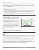
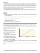
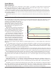
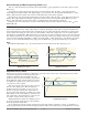
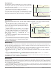
Cool Output Curve
A nonlinear output curve may improve performance when the response of the output device is nonlinear. If a
cool output uses one of the nonlinear curves a PID calculation yields a lower actual output level than a linear
output would provide.
These output curves are used in plastics extruder applications: curve A for oil-cooled extruders and curve
B for water-cooled extruders. Select a nonlinear cool output curve with Cool Output Curve [`C;Cr] (Setup
Menu, Loop Menu).
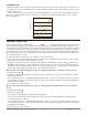
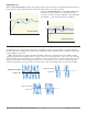
Resetting a Tripped Limit
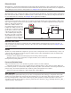
When a limit controller is ordered (PM _ _ _ _ _ - _ [L,M] _ _ _ _ _) output 4 will always be a Form A (normal-
ly open) Mechanical Relay and it will always be internally tied to the limit function. When the limit is in a
safe state the internal coil for this relay will be energized, therefore the relay will be closed. When a condition
occurs that causes the limit to trip, the internal coil will deengerize causing the relay to latch open. When
the condition that caused the limit to trip has been resolved, the relay will remain latched open until manu-
ally reset. The process to reset a latched limit can be different from control to control and is dependent upon
the controller firmware version.
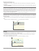
To check the firmware revision of your control do one of the following:
1. Cycle power to the control while observing the number in the top display (this momentary numerical dis-
play reflects the current installed firmware version).
2. Navigate to the Factory Page by simultaneously pushing and holding the Advance Key
‰
and the Reset
Key
RESET
for approximately 8 seconds and then use the up or down arrow key to navigate to the Diagnostic
Menu. Once there, push the Advance Key twice where the revision [`reu] will be shown in the lower dis-
play and the upper display will indicate the current firmware revision.
Execute One of the Following Steps to Reset a Tripped Limit Prior to Firmware Release 11.0:
1. Push the Reset Key
RESET
2. Configure a digital input with the Action Function set to Limit Reset (navigate to the Setup Page under
the Digital I/O Menu).
3. Use a field bus protocol, i.e., Modbus, EtherNet/IP, etc...where a value of zero would be written to the asso-
ciated address (navigate to the Operations Page and look for Limit Clear Request under the Limit Menu to
find appropriate address).
4. Cycle the power to the controller.
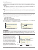
Execute One of the Following Steps to Reset a Tripped Limit with Firmware Release 11.0 and
above:
1. Push the Reset Key
RESET
2. Follow the steps below:
2a. Navigate to the Setup Page and then the Limit Menu
2b. Set Source Function A to the desired device that will reset the limit (Digital I/O or Function Key)
2c. Define the Source Instance
3. Use a field bus protocol, i.e., Modbus, EtherNet/IP, etc...where a value of zero would be written to the asso-
ciated address (navigate to the Operations Page and look for Limit Clear Request under the Limit Menu to
find appropriate address).
4. Cycle the power to the controller.
Actual Output Power
0
20
40
60
80
100
PID Calculation
Linear
Curve 1
Curve 2
Linear
Curve A
Curve B