
Owner manual

Watlow EZ-ZONE
®
PM Integrated Controller • 131 • Chapter 9 Features
Control Methods
Output Configuration
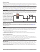
Each controller output can be configured as a heat output, a cool output, an alarm output or deactivated. No
dependency limitations have been placed on the available combinations. The outputs can be configured in
any combination. For instance, all three could be set to cool.
Heat and cool outputs use the set point and Operations parameters to determine the output value. All
heat and cool outputs use the same set point value. Heat and cool each have their own set of control param-
eters. All heat outputs use the same set of heat control parameters and all cool outputs use the same set of
cool output parameters.
Each alarm output has its own set of configuration parameters and set points, allowing independent op-
eration.
Auto (closed loop) and Manual (open loop) Control
The controller has two basic modes of operation, auto mode and manual mode. Auto mode allows the control-
ler to decide whether to perform closed-loop control or to follow the settings of Input Error Failure [FAiL]
(Setup Page, Loop Menu). The manual
mode only allows open-loop control. The EZ-
ZONE
®
PM controller is normally used in
the auto mode. The manual mode is usually
only used for specialty applications or for
troubleshooting.
Manual mode is open-loop control that al-
lows the user to directly set the power level
to the controller’s output load. No adjust-
ments of the output power level occur based
on temperature or set point in this mode.
In auto mode, the controller monitors the
input to determine if closed-loop control is
possible. The controller checks to make cer-
tain a functioning sensor is providing a valid
input signal. If a valid input signal is pres-
ent, the controller will perform closed-loop
control. Closed-loop control uses a process
sensor to determine the difference between
the process value and the set point. Then the controller applies power to a control output load to reduce that
difference.
If a valid input signal is not present, the controller will indicate an input error message in the upper dis-
play and [Attn] in the lower display and respond to the failure according to the setting of Input Error Fail-
ure [FAiL]. You can configure the controller to perform a bumpless transfer [bPLS], switch power to output
a preset fixed level [MAn], or turn the output power off.
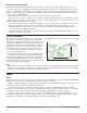
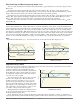
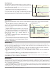
Bumpless transfer will allow the controller to transfer to the manual mode using the last power value cal-
culated in the auto mode if the process had stabilized at a ±5 percent output power level for the time interval
of Time Integral (Operations Page, Loop) prior to sensor failure, and that power level is less than 75 percent.
Reverse Bumpless functionality will take effect when the control is changed from Manual to Auto mode.
The control will preload the Open Loop Set Point value into the Integral Term, which will allow for a bump-
less transition. The normal PID action will then take over to control the output to the Closed Loop Set Point
value.
Note:
Reverse bumpless ignores the transition from Off to Auto.
Input Error Latching [`i;Er] (Setup Page, Analog Input Menu) determines the controller’s response once
a valid input signal returns to the controller. If latching is on, then the controller will continue to indicate an
input error until the error is cleared. To clear a latched alarm, press the Advance Key
‰
then the Up Key
¿.
If latching is off, the controller will automatically clear the input error and return to reading the tempera-
ture. If the controller was in the auto mode when the input error occurred, it will resume closed-loop control.
If the controller was in manual mode when the error occurred, the controller will remain in open-loop control.
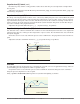
The Manual Control Indicator Light % is on when the controller is operating in manual mode.
Time
Temperature
Bumpless Transfer
40%
Sensor
Break
2 minutes
Locks in
Output
Power
0%
Set Point
Actual Temperature
Output Power
Power
100%