
Owner manual

Watlow EZ-ZONE
®
PM Integrated Controller • 136 • Chapter 9 Features
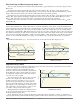
Differential Control
The PM can be configured for Differential Control with enhanced firmware. After configuring the appropri-
ate inputs and their associated internal functions Differential Control allows the PM to drive an output based
on the difference between those analog inputs. See Chapter 10 for application examples.
Ratio Control
The PM control can be configured for Ratio control with enhanced firmware, especially useful in applications
that mix materials. Ratio control is commonly used to ensure that two or more flows are kept at the same ra-
tio even if the flows are changing. See Chapter 10 for application examples.
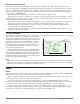
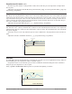
Duplex Control
Certain systems require that a single process output control both heating and cooling outputs. A PM control
with a process output can function as two separate outputs. With a 4 to 20mA output the heating output, for
instance, will operate from 12 to
20mA (0 to +100%) and the cool-
ing outputs will operate from 12
to 4mA (0 to -100%). In some cas-
es this type of output is required
by the device, such as a three-way
valve that opens one way with
a 12 to 20mA signal and opens
the other way with a 4 to 12mA
signal. This feature reduces the
overall system cost by using a sin-
gle output to act as two outputs.
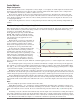
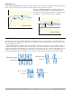
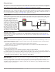
Motorized Valve Control
A motorized valve is used is to regulate the flow of fluid which in turn impacts the loop process value. A
valve is opened or closed by closing contacts to drive the value in the intended direction. See Chapter 10 for
application examples.
Alarms
Alarms are activated when the output level, process value or temperature leaves a defined range. A user can
configure how and when an alarm is triggered, what action it takes and whether it turns off automatically
when the alarm condition is over.
Configure alarm outputs in the Setup Page before setting alarm set points.
Alarms do not have to be assigned to an output. Alarms can be monitored and controlled through the
front panel or by using software.
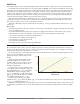
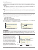
Process and Deviation Alarms
A process alarm uses one or two absolute set points to define an alarm condition.
A deviation alarm uses one or two set points that are defined relative to the control set point. High and
low alarm set points are calculated by adding or subtracting offset values from the control set point. If the set
point changes, the window defined by the alarm set points automatically moves with it.
Select the alarm type with Type [`A;ty] (Setup Page, Alarm Menu).
Alarm Set Points
The alarm high set point defines the process value or temperature that will trigger a high side alarm. The
alarm low set point defines the temperature that will trigger a low side alarm. For deviation alarms, a nega-
tive set point represents a value below closed loop set point. A positive set point represents a value above
closed loop set point. View or change alarm set points with Low Set Point [`A;Lo] and High Set Point [`A;hi]
(Operations Page, Alarm Menu).
hot water
cold water
temperature
transmitter
Fluid Sample Container
®
Input 1 Output 1