
Owner manual
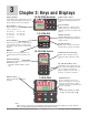

Watlow EZ-ZONE
®
PM Integrated Controller • 47 • Chapter 4 Home Page
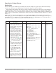
Custom Menu Parameter Options
Description Prompt *
If 4
th
digit of part number is B, E, R or N
Profile Start
[p ;st1]
Profile Action Request
[p ;aC1]
Guarnteed Soak Deviation 1
[gsd1]
If 9
th
digit of part number is T
Current Read
[CU;r1]
* The numerical digit shown in the prompts above (last digit), represents the parameter instance and can be
greater than one.
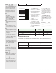
Modifying the Display Pairs
The Home Page, being a customized list of as many as 20 parameters can be configured in pairs of up to 10
via the Display Pairs [d;prs] prompt found in the Diagnostic Menu [diag] (Factory Page). The listing in the
table that follows is what one may typically find in the Home Page as defaults based on controller part num-
bers. It is important to note that some of the prompts shown may not appear simply because the feature is
not being used or is turned off. As an example, the prompt shown in position 7 (loop 1) and position 12 (loop
2) [`C;pr] will not appear unless the Cool algorithm [`C;ag ] is turned on in the Setup Page under the Loop
menu.
If the ninth digit of the part number is C, J, L or M (PM _ _ _ _ _ - _ [C, J, L, M] _ _ _ _ _) the Display Pairs
[d;prs] prompt will default to 2; otherwise, it will be equal to one.
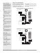
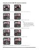
As stated above, the user can define pairs of prompts to appear on the display every time the Advance
‰
key
is pushed. The first pair will always be as defined in the Custom Menu and as stated will default (fac-
tory settings) to the Active Process Value loop 1 [aC;pu], and the Active Set Point loop 1 [aC;sp]. If two chan-
nels are present the first 2 pairs will be the same in that the first pair will represent channel 1 Active Process
Value and Active Set Point and the second being the same for channel 2. If another pair is created where the
Display Pairs [d;prs] prompt is equal to 3 using the default prompts, when the Advance key
‰
is pushed
two times from the Home Page the upper display will reflect the current control mode and the bottom display
would show the output power. When configuring the Custom Menu to your liking it should be noted that if a
writable value is placed on the upper display and is paired with another read only parameter on the lower
display, the arrow keys will affect the setting of the upper display. Also, if 2 changeable (writable) prompts are
displayed in a Pair, i.e., Control Mode on top and Idle Set Point on the bottom, only the lower display (Idle Set
Point) can be changed.
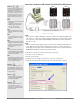
The display can be configured to scroll customized pairs by going to the Factory Page under the Diagnostic
Menu and changing the Display Time [`d ; ti] prompt to something greater than 0 and by changing the Dis-
play Pairs [d;prs] to something greater than 1. If the Display Time [`d ;ti] is set to 2, the display will toggle
every 2 seconds from the first display pair to the second and then the third, etc... If the control has more than
one channel and one of the configured pairs is set as instance 2, the channel indicator (LED) will change
from 1 to 2 reflecting the channel of the pair being displayed. The display will continue to toggle through all
of the custom pairs at the specified time interval.
Possible
Home Page Defaults
(Dependent on Part Number)
Home Page
Display
Parameter Page and Menu
All Models
1 Active Process Value (1)
Numerical
value
Operations Page, Monitor Menu
2 Active Set Point (1)
Numerical
value
Operations Page, Monitor Menu
If 9
th
digit of part number is equal to: PM _ _ _ _ _ - _ [L, M] _ _ _ _ _
3 Process Value (2)
Numerical
value
Operations Page, Monitor Menu
4 Limit Status
[safe]
or
[fail]
Home Page