EZ-ZONE PM ® User’s Guide PID Controller Models TOTAL CUSTOMER SATISFACTION 3 Year Warranty ISO 9001 Registered Company Winona, Minnesota USA 1241 Bundy Boulevard., Winona, Minnesota USA 55987 Phone: +1 (507) 454-5300, Fax: +1 (507) 452-4507 http://www.watlow.com 0600-0058-0000 Rev. M April 2013 Made in the U.S.A.
Safety Information We use note, caution and warning symbols throughout this book to draw your attention to important operational and safety information. A “NOTE” marks a short message to alert you to an important detail. A “CAUTION” safety alert appears with information that is important for protecting your equipment and performance. Be especially careful to read and follow all cautions that apply to your application.
Warranty The EZ-ZONE® PM is manufactured by ISO 9001-registered processes and is backed by a three-year warranty to the first purchaser for use, providing that the units have not been misapplied. Since Watlow has no control over their use, and sometimes misuse, we cannot guarantee against failure. Watlow’s obligations hereunder, at Watlow’s option, are limited to replacement, repair or refund of purchase price, and parts which upon examination prove to be defective within the warranty period specified.
TC Table of Contents Chapter 1: Overview . . . . . . . . . . . . . . . . . . . . . . . . . . . . . . . . . . . . . 3 Standard Features and Benefits . . . . . . . . . . . . . . . . . . . . . . . . . . . . . . . . 3 Getting Started Quickly. . . . . . . . . . . . . . . . . . . . . . . . . . . . . . . . . . . . . 5 Chapter 2: Install and Wire. . . . . . . . . . . . . . . . . . . . . . . .
TC Table of Contents (cont.) Chapter 7: Profiling Page. . . . . . . . . . . . . . . . . . . . . . . . . . . . . . . . . 70 Profile Setup. . . . . . . . . . . . . . . . . . . . . . . . . . . . . . . . . . . . . . . . . . . . . . 70 Starting a Profile. . . . . . . . . . . . . . . . . . . . . . . . . . . . . . . . . . . . . . . . . . . 71 Profiling Menu . . . . . . . . . . . . . .
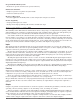
1 Chapter 1: Overview The EZ-ZONE ® PM takes the pain out of solving your thermal loop requirements. Watlow’s EZ-ZONE PM controllers offer options to reduce system complexity and the cost of control-loop ownership. You can order the EZ-ZONE PM as a PID controller or an over-under limit controller, or you can combine both functions in the PM Integrated Limit Controller.
Programmable Menu System • Reduces set up time and increases operator efficiency Full-featured Alarms • Improves operator recognition of system faults • Control of auxiliary devices Heat-Cool Operation • Provides application flexibility with accurate temperature and process control Profile Capability • Preprogrammed process control • Ramp and soak programming with four files and 40 total steps A Conceptual View of the PM The flexibility of the PM’s software and hardware allows a large range of configuratio
Input Events and Output Events Input and output events are internal states that are used exclusively by profiles. The source of an event input can come from a real-world digital input or an output from another function. Likewise, event outputs may control a physical output such as an output function block or be used as an input to another function. Getting Started Quickly The PM control has a page and menu structure that is listed below along with a brief description of its purpose.
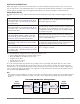
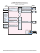
EZ-ZONE® PM PID Model System Diagram Universal Sensor Input, Configuration Communications, Red/Green 7-Segment Display Output Functions Input Functions Input sensor None Profile start/stop Profile start Profile hold/resume Profile disable TRU-TUNE+® disable Control outputs off Manual/auto mode Tune Idle set point Force alarm Loop & alarms off Silence alarm Alarm reset Lock keypad Restore user settings Network remote user interface, personal computer, programmable logic controller, humanmachine interfa
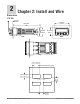
2 Dimensions Chapter 2: Install and Wire 1/32 DIN 15.9 mm 0.63 in 53.3 mm 2.10 in 101.6 mm 4.00 in 31.2 mm 1.23 in 30.9 mm 1.22 in Side Front Top 44.96 to 45.47 mm (1.77 to 1.79 inches) Recommended panel spacing 22.2 to 22.5 mm (0.87 to0.89 inches) panel thickness 1.53 to 9.52 mm (0.060 to 0.375) 21.6 mm (0.85 in) Minimum 21.6 mm (0.
1/16 DIN 15.8 mm (0.62 in) 101.6 mm (4.00 in) 53.3 mm (2.10 in) 53.3 mm (2.10 in) Side Front 51.2 mm (2.02 in) Top L1 L3 K1 K3 99 J1 J3 CF 98 L2 L4 CD K2 K4 CE T1 T2 B5 S1 S2 D6 R1 R2 D5 Back 44.96 to 45.47 mm (1.77 to 1.79 inches) 44.96 to 45.47 mm (1.77 to 1.79 inches) panel thickness 1.53 to 9.52 mm (0.060 to 0.375) 21.6 mm (0.85 in) Minimum 21.6 mm (0.
1/8 DIN (PM8) Vertical 15.75 mm (0.62 in) 1.52 mm (0.06 in) 53.34 mm (2.10 in) 100.33 mm (3.95 in) 10.16 mm (0.40 in) 30.73 mm (1.21 in) 54.86 mm (2.16 in) 101.60 mm (4.00 in) 1/8 DIN (PM8) Vertical Recommended Panel Spacing 44.96 to 45.60 mm (1.77 to 1.79 inches) 92.00 to 92.80 mm (3.62 to 3.65 inches) Panel thickness (0.060 in) 1.53 mm to (0.375 in) 9.52 mm 21.6 mm (0.85 in) Minimum 21.6 mm (0.
1/8 DIN (PM9) Horizontal 15.75 mm (0.62 in) 1.52 mm (0.06 in) 100.33 mm (3.95 in) 54.86 mm (2.16 in) 53.34 mm (2.10 in) 10.16 mm (0.40 in) 30.73 mm (1.21 in) 101.60 mm (4.00 in) 1/8 DIN (PM9) Horizontal Recommended Panel Spacing 92.00 to 92.80 mm (3.62 to 3.65 inches) 44.96 to 45.60 mm (1.77 to 1.79 inches) Panel thickness (0.060 in) 1.53 mm to (0.375 in) 9.52 mm 21.6 mm (0.85 in) Minimum 21.6 mm (0.
1/4 DIN (PM4) 15.75 mm (0.62 in) 1.52 mm (0.06 in) 100.33 mm (3.95 in) 100.33 mm (3.95 in) 12.70 mm (0.50 in) 30.73 mm (1.21 in) 100.84 mm (3.97 in) 1/4 DIN (PM4) Recommended Panel Spacing 92.0 to 93.0 mm (3.62 to 3.65 inches) 92.0 to 93.0 mm (3.62 to 3.65 inches) 21.6 mm (0.85 inches) Minimum Panel thickness .060 (1.53) to .375 (9.52) 21.6 mm (0.
Installation 1. Make the panel cutout using the mounting template dimensions in this chapter. Insert the case assembly into the panel cutout. 2. While pressing the case assembly firmly against the panel, slide the mounting collar over the back of the controller. If the installation does not require a NEMA 4X seal, simply slide together until the gasket is compressed. Slide the mounting collar over the back of the controller. Place the blade of a screwdriver in the notch of the mounting collar assembly.
Removing the Mounted Controller from Its Case 1. From the controller's face, pull out the tabs on each side until you hear it click. Pull out the tab on each side until you hear it click. Grab the unit above and below the face and pull forward. 2. On a PM6 control once the sides are released grab the unit above and below the face with two hands and pull the unit out. On the PM4/8/9 controls slide a screwdriver under the pry tabs and turn. çWarning: • This equipment is suitable for use in class 1, div.
Wiring Terminal Definitions for Slots A Slot A Output Terminal Function Configuration common (Any switched dc output can use this common.
Back View Slot Orientation 1/8 DIN Vertical PM8 Power A C E D B Dig I/O 5 & 6 485 Comms Dig I/O 5 & 6 485 Comms C Input 1 Input 1 E Output 2 Output 2 A Output 1 Output 1 Power Back View Slot Orientation 1/8 DIN Horizontal PM9 Input 1 A D E C Dig I/O 5 & 6 485 Comms Communications Card Output 2 Digital I/O 7 - 12 Output 1 D B Power Back View Slot Orientation 1/4 DIN Horizontal PM4 Output 3 Output 4 Input 2 B EZ-ZONE PM Isolation Blocks Digital Inputs & Outputs 5-6 No Iso
Warning: Óç Use National Electric (NEC) or other country-specific standard wiring and safety practices when wiring and connecting this controller to a power source and to electrical sensors or peripheral devices. Failure to do so may result in damage to equipment and property, and/or injury or loss of life. Low Power Slot C 98 99 Note: Adjacent terminals may be labeled differently, depending on the model number. Note: To prevent damage to the controller, do not connect wires to unused terminals.
Warning: Óç Input 1 Thermocouple Slot A Use National Electric (NEC) or other country-specific standard wiring and safety practices when wiring and connecting this controller to a power source and to electrical sensors or peripheral devices. Failure to do so may result in damage to equipment and property, and/or injury or loss of life. • • • • - Note: Maximum wire size termination and torque rating: • 0.0507 to 3.30 mm2 (30 to 12 AWG) single-wire termination or two 1.31 mm2 (16 AWG) • 0.8 Nm (7.0 lb.
Warning: Óç Input 1 Thermistor Slot A Use National Electric (NEC) or other country-specific standard wiring and safety practices when wiring and connecting this controller to a power source and to electrical sensors or peripheral devices. Failure to do so may result in damage to equipment and property, and/or injury or loss of life. Note: Maximum wire size termination and torque rating: • 0.0507 to 3.30 mm2 (30 to 12 AWG) single-wire termination or two 1.31 mm2 (16 AWG) • 0.8 Nm (7.0 lb.-in.
Warning: Óç Digital Output 5, 6 Slot C Use National Electric (NEC) or other country-specific standard wiring and safety practices when wiring and connecting this controller to a power source and to electrical sensors or peripheral devices. Failure to do so may result in damage to equipment and property, and/or injury or loss of life. 98 99 CF CD CE B5 Note: Maximum wire size termination and torque rating: • 0.0507 to 3.30 mm2 (30 to 12 AWG) single-wire termination or two 1.31 mm2 (16 AWG) • 0.8 Nm (7.
Warning: Óç Use National Electric (NEC) or other country-specific standard wiring and safety practices when wiring and connecting this controller to a power source and to electrical sensors or peripheral devices. Failure to do so may result in damage to equipment and property, and/or injury or loss of life. Note: Output 1 Switched DC/Open Collector Slot A common dc - (open collector) dc + X1 W1 Y1 Maximum wire size termination and torque rating: • 0.0507 to 3.
Warning: Óç Use National Electric (NEC) or other country-specific standard wiring and safety practices when wiring and connecting this controller to a power source and to electrical sensors or peripheral devices. Failure to do so may result in damage to equipment and property, and/or injury or loss of life. Output 1 Solid-State Relay, Form A Slot A normally open L1 common K1 Note: Maximum wire size termination and torque rating: • 0.0507 to 3.30 mm2 (30 to 12 AWG) single-wire termination or two 1.
Warning: Óç Use National Electric (NEC) or other country-specific standard wiring and safety practices when wiring and connecting this controller to a power source and to electrical sensors or peripheral devices. Failure to do so may result in damage to equipment and property, and/or injury or loss of life.
Warning: Óç Use National Electric (NEC) or other country-specific standard wiring and safety practices when wiring and connecting this controller to a power source and to electrical sensors or peripheral devices. Failure to do so may result in damage to equipment and property, and/or injury or loss of life. Note: Maximum wire size termination and torque rating: • 0.0507 to 3.30 mm2 (30 to 12 AWG) single-wire termination or two 1.31 mm2 (16 AWG) • 0.8 Nm (7.0 lb.-in.
Warning: Óç A Network Using Watlow's Standard Bus and an RUI/Gateway Power Supply EZ-ZONE ST ST_ _ - (B or F) _ M _ -_ _ _ _ Use National Electric (NEC) or other country-specific standard wiring and safety practices when wiring and connecting this controller to a power source and to electrical sensors or peripheral devices. Failure to do so may result in damage to equipment and property, and/or injury or loss of life.
Warning: Óç Connecting a Computer to PM Controls Using B&B 485 to USB Converter Address 2 Address 1 Use National Electric (NEC) or other country-specific standard wiring and safety practices when wiring and connecting this controller to a power source and to electrical sensors or peripheral devices. Failure to do so may result in damage to equipment and property, and/or injury or loss of life. USB Port Slot C Slot B Slot A Slot C Maximum wire size termination and torque rating: • 0.0507 to 3.
3 Chapter 3: Keys and Displays Upper (Left, 32nd DIN) Display: 1/32 DIN (PM3) In the Home Page, displays the process value, otherwise displays the value of the parameter in the lower display. Zone Display: Indicates the controller zone.
Responding to a Displayed Message An active message will cause the display to toggle between the normal settings and the active message in the upper display and [Attn] in the lower display. Your response will depend on the message and the controller settings. Some messages, such as Ramping and Tuning, indicate that a process is underway.
4 Chapter 4: Home Page Default Home Page Parameters Watlow’s patented user-defined menu system improves operational efficiency. The user-defined Home Page provides you with a shortcut to monitor or change the parameter values that you use most often. The default Home Page is shown on the following page. When a parameter normally located in the Setup Page or Operations Page is placed in the Home Page, it is accessible through both.
Modifying the Home Page Follow the steps below to modify the Home Page: 1. Push and hold the Advance ‰ key and the Infinity ˆ key for approximately six seconds. Upon entering the Factory Page the first menu will be the Custom Menu [Cust] . 2. Push the Advance ‰ key where the lower display will show [Cust] and the upper display will show [1] . 3. Push the Advance ‰ button where the prompt for the Process Value [aC; p u] will be displayed on top and Parameter [`par] in the bottom.
Modifying the Display Pairs The Home Page, being a customized list of as many as 20 parameters can be configured in pairs of up to 10 via the Display Pairs [d;prs] prompt found in the Diagnostic Menu [diag] (Factory Page). The listing in the table that follows is what one may typically find in the Home Page as defaults based on controller part numbers. It is important to note that some of the prompts shown may not appear simply because the feature is not being used or is turned off.
Home Page Defaults Home Page Display Parameter Page and Menu All Models 1 Active Process Value (1) Numerical value Operations Page, Monitor Menu 2 Active Set Point (1) Numerical value Operations Page, Monitor Menu 3 Control Mode (1) [C;M1] Operations Page, Monitor Menu 4 Heat Power (1) [h;pr1] Operations Page, Monitor Menu 5 Cool Power (1) [C;pr1] Operations Page, Monitor Menu 6 Autotune (1) [aut1] Operations Page, Loop Menu 7 Idle Set Point (1) [id;s1] Operations Page, Loop Me
Navigating the EZ-ZONE® PM PID Controller Applies to All Models - 1/16 DIN Shown Below ® ® ® ® [``Ai] [``70] [``70] [Cust] [`Set] [``72] [``72] [fCty] Home Page from anywhere: Press the Infinity Factory Page from Home Page: Press both the Advance ‰ and Infinity ˆ keys for six seconds. Key ˆ for two seconds to return to the Home Page. ® ® [``70] [``Ai] [``72] [oper] Operations Page from Home Page: Press both the Up ¿ and Down ¯ keys for three seconds.
Conventions Used in the Menu Pages To better understand the menu pages that follow review the naming conventions used. When encountered throughout this document, the word "default" implies as shipped from the factory. Each page (Operations, Setup, Profile and Factory) and their associated menus have identical headers defined below: Header Name Definition Display Visually displayed information from the control. Parameter Name Describes the function of the given parameter.
Range Within this column notice that on occasion there will be numbers found within parenthesis. This number represents the enumerated value for that particular selection. Range selections can be made simply by writing the enumerated value of choice using any of the available communications protocols. As an example, turn to the Setup Page and look at the Analog Input [`Ai] menu and then the Sensor Type [Sen] prompt.
5 Chapter 5: Operations Page Navigating the Operations Page To navigate to the Operations Page, follow the steps below: 1. From the Home Page, press both the Up ¿ and Down ¯ keys for three seconds. [``Ai] will appear in the upper display and [oPEr] will appear in the lower display. 2. Press the Up ¿ or Down ¯ key to view available menus. 3. Press the Advance Key ‰ to enter the menu of choice. 4.
Operations Page Display Parameter Name Description Range Default Modbus Relative Address CIP Class Instance Attribute hex (dec) Instance 1 Map 1 Map 2 360 360 Data Type & Read/ Write Profibus Index Parameter ID 0x68 (104) 1 1 0 4001 float R [``Ai] [oPEr] Analog Input Menu [`Ain] [ Ain] Analog Input (1) Analog Input Value View the process value. Note: -1,999.000 to 9,999.000°F or units -1,128.000 to 5,537.
Operations Page Display Parameter Name Description Range [``o;u] [ o.v] Linearization (1) Output Value View the value of this function's output. -1,999.000 to 9,999.000°F or units -1,128.000 to 5,537.000°C No Display Linearization (1) Output Error View reported cause for Linearization output malfunction.
Operations Page Display Parameter Name Description Range Default Modbus Relative Address CIP Class Instance Attribute hex (dec) Profibus Index Parameter ID Data Type & Read/ Write [`dio] [oPEr] Digital Input/Output Menu [`do;S] [ do.S] Digital Output (5 to 6) Output State View the state of this output. [`off] Off (62) [``on] On (63) ---- Instance 5 Map 1 Map 2 1012 1132 Offset to next instance equals +30 0x6A (106) 5 to 6 7 90 6007 uint R [`di;S] [ di.
Operations Page Display Parameter Name Description Range Default Modbus Relative Address CIP Class Instance Attribute hex (dec) Profibus Index Parameter ID Data Type & Read/ Write No Display Monitor (1) -1,999.000 to Set Point Active 9,999.000°F or units Read the current active set -1,128.000 to point. 5,537.000°C Instance 1 Map 1 Map 2 2172 2652 0x6B (107) 1 7 ---- 7018 float R No Display Monitor (1) Autotune Status Read the present status of Autotune.
Operations Page Display Parameter Name Description Range Default Modbus Relative Address CIP Class Instance Attribute hex (dec) Profibus Index Parameter ID Data Type & Read/ Write [`id;S] [ id.S] Control Loop (1) Idle Set Point Set a closed loop set point that can be triggered by an event state. Low Set Point to High Set Point (Setup Page) 75.0°F or units 24.0°C Instance 1 Map 1 Map 2 2176 2656 0x6B (107) 1 9 50 7009 float RWES [`h;Pb] [ h.
Operations Page Parameter Name Description Display Range Default Modbus Relative Address CIP Class Instance Attribute hex (dec) Profibus Index Parameter ID Data Type & Read/ Write No Display Control Loop (1) Loop Error Open Loop detect deviation has been exceeded. [none] None (61) [`lp;o] Open Loop (1274) [`lp;r] Reversed Sensor (1275) ---- Instance 1 Map 1 Map 2 ---2408 0x6C (108) 1 0x30 (48) ---- 8030 uint R No Display Control Loop (1) Clear Loop Error Current state of limit output.
Operations Page Display No Displayed Parameter Name Description Alarm (1 to 4) Alarm Clearable Current state of alarm Range Default ---- [``no] No (59) [`YES] Yes (106) Modbus Relative Address CIP Class Instance Attribute hex (dec) Instance 1 Map 1 Map 2 1502 1902 Data Type & Read/ Write Profibus Index Parameter ID 0x6D (109) 1 to 4 0xC (12) ---- 9012 uint R 0x6D (109) 1 to 4 0xD (13) ---- 9013 uint W 0x6D (109) 1 to 4 0xE (14) ---- 9014 uint W 0x6D (109) 1 to 4 0x0B (11) ---- 90
Operations Page Display Parameter Name Description Range Default Modbus Relative Address CIP Class Instance Attribute hex (dec) Profibus Index Parameter ID Data Type & Read/ Write * Available with PM8/9 only * Some parameters in the Profile Status Menu can be changed for the currently running profile, but should only be changed by knowledgeable personnel and with caution.
Operations Page Display Parameter Name Description Range Default Modbus Relative Address CIP Class Instance Attribute hex (dec) Profibus Index Parameter ID Data Type & Read/ Write [min] [ Min] Profile Status Minutes Step time remaing in minutes. 0 to 59 0 Instance 1 Map 1 Map 2 ---4492 0x7A (122) 1 0x4D (77) ---- 22077 uint RW [`seC] [ SEC] Profile Status Seconds Step time remaing in seconds.
6 Chapter 6: Setup Page Navigating the Setup Page To go to the Setup Page from the Home Page, press both the Up ¿ and Down ¯ keys for six seconds. [``Ai] will appear in the upper display and [`Set] will appear in the lower display. • Press the Up ¿ or Down ¯ key to view available menus. On the following pages top level menus are identified with a yellow background color. •Press the Advance Key ‰ to enter the menu of choice.
[`o;Lo] Output Low Power Scale [`o;hi] Output High Power Scale [otpt] Output 1 process [`o;ty] Output Type [``Fn] Output Function [``Fi] Output Function Instance [`S;Lo] Scale Low [`S;hi] Scale High [`r;Lo] Range Low [`r;hi] Range High [`o;lo] Output Low Power Scale [`o;ho] Output High Power Scale [`o;CA] Calibration Offset [gLbL] [`Set] Global Menu [`C_F] Display Units [AC;LF] AC Line Frequency [r;typ] Ramping Type [p;typ] Profile Type [`gse] Guaranteed S
Setup Page Display Parameter Name Description Range Default CIP Modbus RelaClass tive Instance Address Attribute hex (dec) Profibus Index Parameter ID Data Type & Read/ Write [``Ai] [`Set] Analog Input Menu [`Sen] [ SEn] Analog Input (1) Sensor Type Set the analog sensor type to match the device wired to this input. Note: There is no open-sensor detection for process inputs.
Setup Page Display Parameter Name Description Range Default CIP Modbus RelaClass tive Instance Address Attribute hex (dec) Profibus Index Parameter ID Data Type & Read/ Write [`r;hi] [ r.hi] Analog Input (1) -1,999.000 to 9,999.000 Range High Set the high range for this function block's output. 9,999 Instance 1 0x68 (104) 1 Map 1 Map 2 0x12 (18) 394 394 9 4018 float RWES [`P;EE] [ P.EE] Analog Input (1) Process Error Enable Turn the Process Error Low feature on or off.
Setup Page Display [`Ain] [ Ain] Parameter Name Description Analog Input (1) Analog Input Value View the process value. Note: Range Default -1,999.000 to 9,999.000°F or units -1,128.000 to 5,537.
Setup Page CIP Modbus RelaClass tive Instance Address Attribute hex (dec) Data Type & Read/ Write Profibus Index Parameter ID Instance 1 0x86 (134) 1 Map 1 Map 2 ---3596 0x13 (19) 160 34019 float RWES 2.0 Instance 1 0x86 (134) 1 Map 1 Map 2 ---3578 0xA (10) 161 34010 float RWES -1,999.000 to 9,999.000 2.0 Instance 1 0x86 (134) 1 Map 1 Map 2 ---3598 0x14 (20) 162 34020 float RWES Linearization (1) Input Point 4 Set the value that will be mapped to output 4. -1,999.000 to 9,999.000 3.
Setup Page CIP Modbus RelaClass tive Instance Address Attribute hex (dec) Data Type & Read/ Write Profibus Index Parameter ID Instance 1 0x86 (134) 1 Map 1 Map 2 ---3590 0x10 (16) 173 34016 float RWES 8.0 Instance 1 0x86 (134) 1 Map 1 Map 2 ---3610 0x1A (26) 174 34026 float RWES -1,999.000 to 9,999.000 9.0 Instance 1 0x86 (134) 1 Map 1 Map 2 ---3592 0x11 (17) 175 34017 float RWES -1,999.000 to 9,999.000 9.
Setup Page Display Parameter Name Description Range Default CIP Modbus RelaClass tive Instance Address Attribute hex (dec) Data Type & Read/ Write Profibus Index Parameter ID 82 6001 uint RWES 83 6005 uint RWES 84 6006 uint RWES 85 6002 uint RWES 86 6003 float RWES [`dio] [`Set] Digital Input/Output Menu [`dir] [ dir] [``Fn] [ Fn] [``Fi] [ Fi] [`o;Ct] [ o.Ct] [`o;tb] [ o.
Setup Page Display [`o;Lo] [ o.Lo] [`o;hi] [ o.hi] [`leu] [ LEv] Parameter Name Description Range Digital Output (5 to 6) Output Low Power Scale The power output will never be less than the value specified and will represent the value at which output scaling begins. 0.0 to 100.0 Digital Output (5 to 6) Output High Power Scale The power output will never be greater than the value specified and will represent the value at which output scaling stops. 0.0 to 100.
Setup Page Display Parameter Name Description [``Fn] [ Fn] Digital Input (5 to 6) Action Function Select the function that will be triggered by a true state for Digital Input 5 and or 6.
Setup Page Display Parameter Name Description Range Default CIP Modbus RelaClass tive Instance Address Attribute hex (dec) Profibus Index Parameter ID Data Type & Read/ Write [`C;Ag] [ C.Ag] Control Loop (1) Cool Algorithm Set the cool control method. [`oFF] Off (62) [`Pid] PID (71) [on;of] On-Off (64) Off Instance 1 0x97 (151) 1 Map 1 Map 2 4 1886 2366 73 8004 uint RWES [`C;Cr] [ C.Cr] Control Loop (1) Cool Output Curve Select a cool output curve to change the responsiveness of the system.
Setup Page CIP Modbus RelaClass tive Instance Address Attribute hex (dec) Data Type & Read/ Write Profibus Index Parameter ID 71 8008 float RWES Instance 1 0x97 (151) 1 Map 1 Map 2 0x10 (16) 1910 2390 ---- 8022 uint RWES 0 Instance 1 0x97 (151) 1 Map 1 Map 2 1912 2392 0x11 (17) ---- 8034 uint RWES Control Loop (1) 1 to 6 TRU-TUNE+™ Gain Select the responsiveness of the TRU-TUNE+™ adaptive tuning calculations. More responsiveness may increase overshoot.
Setup Page Display Parameter Name Description Range Default CIP Modbus RelaClass tive Instance Address Attribute hex (dec) Profibus Index Parameter ID Data Type & Read/ Write [`UFA] [UFA] Control Loop (1) User [`oFF] Off, sets output User Failure Action power to 0% (62) Select what the controller [bPLS] Bumpless Transfer, outputs will do when the maintains same output user switches control to power, if it was less than manual mode.
Setup Page Display Parameter Name Description Range Default CIP Modbus RelaClass tive Instance Address Attribute hex (dec) Profibus Index Parameter ID Data Type & Read/ Write [``rP] [ rP] Control Loop (1) [`oFF] Off (62) Ramp Action [`Str] Startup (88) Select when the control[StPt] Set Point Change ler's set point will ramp to (85) the defined end set point. [both] Both (13) Off Instance 1 0x6B (107) 1 Map 1 Map 2 2186 2666 0xE (14) 56 7014 uint RWES [`r;SC] [ r.
Setup Page Display Parameter Name Description Range Default CIP Modbus RelaClass tive Instance Address Attribute hex (dec) Data Type & Read/ Write Profibus Index Parameter ID 83 6005 uint RWES 84 6006 uint RWES 85 6002 uint RWES 86 6003 float RWES 87 6009 float RWES [otpt] [`Set] Output Menu [``Fn] [ Fn] [``Fi] [ Fi] [`o;Ct] [ o.Ct] [`o;tb] [ o.tb] [`o;Lo] [ o.
Setup Page Display [`o;hi] [ o.hi] Parameter Name Description Output Digital (1 to 2) Output High Power Scale The power output will never be greater than the value specified and will represent the value at which output scaling stops. Range Default 0.0 to 100.0% 100.
Setup Page Display Parameter Name Description Range Default CIP Modbus RelaClass tive Instance Address Attribute hex (dec) Profibus Index Parameter ID Data Type & Read/ Write [`r;Lo] [ r.Lo] Output Process (1) -1,999.000 to 9,999.000°F Range Low or units Set the minimum value -1,128.000 to 5,537.000°C of the retransmit value range in process units. When the retransmit source is at this value, the retransmit output will be at its Scale Low value. 0.
Setup Page Display Parameter Name Description Range Default CIP Modbus RelaClass tive Instance Address Attribute hex (dec) Profibus Index Parameter ID Data Type & Read/ Write [`Sr;A] [ Sr.A] Alarm (1 to 4) Alarm Source Select what will trigger this alarm. Instance 1 0x6D (109) [``Ai] Analog Input (142) If Alarm type is 1 to 4 Map 1 Map 2 [PWr] Power (73) set to 1512 1912 0x11 (17) [``Pu] Process Value Devia(241) tion or [`Lnr] Linearization (238) Process.
Setup Page Range Default CIP Modbus RelaClass tive Instance Address Attribute hex (dec) Alarm (1 to 4) Alarm Low Set Point If Alarm Type (Setup Page, Alarm Menu) is set to: process - set the process value that will trigger a low alarm. deviation - set the span of units from the closed loop set point that will trigger a low alarm. A negative set point represents a value below closed loop set point. A positive set point represents a value above closed loop set point. -1,999.000 to 9,999.
Setup Page Display Parameter Name Description Range Default Instance 1 0x6D (109) 1 to 4 Map 1 Map 2 1510 1910 0x10 (16) On [A;dSP] Alarm (1 to 4) [`oFF] Off (62) [A.dSP] Display [``on] On (63) Display an alarm message when an alarm is active. CIP Modbus RelaClass tive Instance Address Attribute hex (dec) Data Type & Read/ Write Profibus Index Parameter ID 30 9016 uint RWES 31 9021 uint RWES 137 10001 uint RWES Offset to next instance (Map 1 equals +50, for Map 2 equals +60) [`A;dL] [ A.
Setup Page Display [``Fn] [ Fn] Function Key (1 to 2) Action Function Program the EZ Key to trigger an action. Functions respond to a level state change or an edge level change.
Setup Page Display Parameter Name Description Range Default CIP Modbus RelaClass tive Instance Address Attribute hex (dec) Profibus Index Parameter ID Data Type & Read/ Write Time Instance 1 0x7A (122) 1 Map 1 Map 2 26 (38) ---4414 ---- 22038 uint RWE Global [StPt] Set Point (85) Profile Type [`Pro] Process (75) Set the profile startup to be based on a set point or a process value.
Setup Page Display Parameter Name Description [C;led] Global [C.LEd] Communications LED Action Turns comms LED on or off for selected comms ports.
Setup Page Display Parameter Name Description Range Default CIP Modbus RelaClass tive Instance Address Attribute hex (dec) Profibus Index Parameter ID Data Type & Read/ Write [Ad;M] [Ad.M] Communications (1) 1 to 247 Modbus Address Set the network address of this controller. Each device on the network must have a unique address.
Setup Page Display Parameter Name Description Range Default 0 to 59 [Min] [Min] Real Time Clock Minutes Set the current time. [dow] [doW] Real Time Clock [`sun] Sunday (1565) Day of Week [mon] Monday (1559) Set the current day of the [`tue] Tuesday (1560) week.
7 Chapter 7: Profiling Page Navigating the Profiling Page Note: Some of these menus and parameters may not appear, depending on the controller's options. See model number information in the Appendix for more information. If there is only one instance of a menu, no submenus will appear. Profile Setup First, consider some foundational profile setup features that once configured, will apply to all configured profiles.
To navigate to the Profile Page from the front panel, follow the steps below: 1. From the Home Page, press and hold the Advance Key ‰ for approximately five seconds. The profile prompt [ProF] will appear in the lower display and the profile number (e.g. [``p1]) appears in the upper display. 2. Press the Up ¿ or Down ¯ key to change to another profile (1 to 4). 3. Press the Advance Key ‰ to move to the selected profiles first step. 4. Press the Up ¿ or Down ¯ keys to move through and select the step type.
Note: The state of the EZ-Function Key (high or low) is maintained with each successive push of the key. Configuring a Digital Input to Start and Stop a Profile 1. Navigate to the Setup Page and then the Digital I/O menu. From the Home Page, press and hold the ¿ or Down ¯ key for approximately six seconds where the upper display will show [``ai] and the lower display will show [`set] . 2. Press the Up ¿ or Down ¯ key to navigate to the Digital I/O menu.
Ending a Profile from the Operations Page 1. Navigate to the Operations Page and then the Profile Status menu. From the Home Page, press and hold the ¿ or Down ¯ key for approximately three seconds where the upper display will show [``ai] and the lower display will show [oper] . 2. Press the Up ¿ or Down ¯ key to navigate to the Profile Status [ p ; s ta] menu. 3. Press the Advance Key will show [ p ; s tr] . ‰ to enter this menu. The upper display will show [```1] and the lower display 4.
Profiling Page Display Parameter Name Description Range Default Modbus Relative Address ---- ---- CIP Class ParamInstance eter ID Attribute hex (dec) Data Type & Read/ Write [``P1] [prof] Profiling Menu [``p1] Profile [1 to 4] Step Select a step to edit or view. [ P1] to [``p4] [ P4] [S;typ] [S.typ] [t;SP1] [t.
Profiling Page Display Parameter Name Description [rate] [rAtE] Step Type Parameters Rate When Step Type is Rate, enter the rate for ramping in degrees or units per minute. W;P1] [W.P1] WE;1] [WE.1] Range Default 0 to 9,999.000°F or units per minute 0 to 5,555.000°C per minute 0.0 0.0°F or units -18.0°C Step Type Parameters Wait Event 2 When Step Type is Wait for Event or Wait For Both, select the event state that must be satisfied during this step.
Profiling Page Display [~~JS] [ JS] [~~JC] [ JC] [~End] [ End] Parameter Name Description Range Default 1 to 40 Step Type Parameters Jump Step When Step Type is Jump Loop, this setting specifies which step to jump back to. Jump Step must be a lower step number than the current step number.
Display Step Type Description Parameters in Step Type ---- [UStP] [UStP] Step Types Unused Step This is an empty step that can be used to plan for future steps to be inserted or temporarily deactivate a step in a profile. Change step type back when the step should be active again.
8 Chapter 8: Factory Page Navigating the Factory Page To go to the Factory Page from the Home Page, press and hold both the Advance ‰ and Infinity ˆ keys for six seconds. • Press the Advance Key ‰ to enter the menu of choice. • If a submenu exists (more than one instance), press the Up ¿ or Down ¯ key to select and then press the Advance Key ‰ to enter. • Press the Up ¿ or Down ¯ key to move through available menu prompts.
Factory Page Display Parameter Name Description Range Default Modbus Relative Address CIP Data Class Type Profibus ParamInstance & Index eter ID Attribute Read/ hex (dec) Write [Cust] [fcty] Custom Menu [`par] [ Par] Custom Parameter 1 to 20 Select the parameters that will appear in the Home Page. The Parameter 1 value will appear in the upper display of the Home Page. It cannot be changed with the Up and Down Keys in the Home Page.
Factory Page Display Parameter Name Description Range Default Modbus Relative Address CIP Data Class Type Profibus ParamInstance & Index eter ID Attribute Read/ hex (dec) Write [LoC;P] [LoC.P] Security Setting Profiling Page Change the security level of the Profiling Page. 1 to 3 3 ---- ---- ---- 3008 uint RWE [pas;e] [LoC.P] Security Setting Password Enable Set to on to require a password for menu changes.
Factory Page Display Parameter Name Description [pas;a] [PAS.A] Security Setting Administrator Password Used to acquire full access to all menus including disabling or changing passwords.
Factory Page Display Parameter Name Description No Display Diagnostics Firmware ID Display the Firmware ID.
9 Chapter 9: Features Changing PM PID Model Number to PM Express. . . . . . . . . . . . . . . . . 84 How to Change the Control Model Number to a PM Express. . . . . . . . . 85 How to Restore Original PM Model Number . . . . . . . . . . . . . . . . . . . . . 85 Saving and Restoring User Settings. . . . . . . . . . . . . . . . . . . . . . . . . . 85 Programming the Home Page. . . . . . . . . . . . . . . . . . . . . . .
Changing PM PID Model Number to PM Express EZ-ZONE PM firmware revisions of 13 and above allow the user to switch between a PM PID control to a PM Express. Switching to a PM Express eliminates the complexity of the PM PID control by allowing the user to operate with a simplified menu structure. Note: When switching from an integrated control to an Express version, optional PM hardware (even though installed) and firmware features not available in a PM Express will no longer work.
How to Change the Control Model Number to a PM Express 1. Enter Factory Page [FCty ] , Calibration Menu [`CAL] via front panel or using EZ-ZONE Configurator Software. 2. Once there, using the green advance button navigate to the Part Number [``Pn] prompt (lower display). The upper display will show factory [ fCtY] indicating the factory model number as shown on the side of the control is currently in effect. 3.
Programming the Home Page Watlow’s patented user-defined menu system improves operational efficiency. The user-defined Home Page provides you with a shortcut to monitor or change the parameter values that you use most often. You can create your own Home Page with as many as 20 of the active parameters. When a parameter normally located in the Setup Page or Operations Page is placed in the Home Page, it is accessible through both.
Manual Tuning In some applications, the autotune process may not provide PID parameters for the process characteristics you desire. If that is the case, you may want to tune the controller manually. 1. Apply power to the controller and establish a set point typically used in your process. 2. Go to the Operations Page, Loop Menu, and set Heat Proportional Band [`h;Pb] and/or Cool Proportional Band [`C;Pb] to 5. Set Time Integral [``ti] to 0. Set Time Derivative [``td] to 0. 3.
Before Tuning Before autotuning, the controller hardware must be installed correctly, and these basic configuration parameters must be set: • Sensor Type [`SEn] (Setup Page, Analog Input Menu), and scaling, if required; • Function [``Fn] (Setup Page, Output Menu) and scaling, if required. How to Autotune a Loop 1. Enter the desired set point or one that is in the middle of the expected range of set points that you want to tune for. 2. Enable TRU-TUNE+ ®. 3. Initiate an autotune.
sible to minimize error. In addition, a precision volt/ohm meter capable of reading values to 4 decimal places or better is recommended. Prior to calibration, connect this volt/ohm meter to the precision source to verify accuracy. Actual input values do NOT have to be exactly the recommended values, but it IS critical that the actual value of the signal connected to the controller be accurately known to at least four digits.
Calibration of Analog Inputs: (cont.) 15. Validate calibration process by utilizing a calibrator to the analog input. 16. Enter calibration offset as recorded in step 2 if required to compensate for sensor error. Setting Electrical Input Slope [ELi;S] to 1.000 and Electrical Input Offset [ELi; o ] to 0.000, restores factory calibration as shipped from factory. Filter Time Constant Filtering smoothes an input signal by applying a first-order filter time constant to the signal.
Scale High and Scale Low (cont.) to 20 mA, 0 to 5V, 1 to 5V and 0 to 10V. You can create a scale range representing other units for special applications. You can reverse scales from high values to low values for analog input signals that have a reversed action. For example, if 50 psi causes a 4 mA signal and 10 psi causes a 20 mA signal. Scale low and high low values do not have to match the bounds of the measurement range.
Duplex (cont.) Outputs 1 and 3 can be ordered as process outputs. Select duplex [dUPL] as the Output Function [``Fn] (Setup Page, Output Menu). Set the output to volts [uoLt] or milliamps [`MA] with Output Type [`o;ty]. Set the range of the process output with Scale Low [`S;Lo] and Scale High [`S;hi]. NO-ARC Relay A NO-ARC relay provides a significant improvement in the life of the output relay over conventional relays.
Cool Output Curve A nonlinear output curve may improve performance when the response of the output device is nonlinear. If a cool output uses one of the nonlinear curves a PID calculation yields a lower actual output level than a linear output would provide. These output curves are used in plastics extruder applications: curve A for oil-cooled extruders and curve B for water-cooled extruders. Select a nonlinear cool output curve with Cool Output Curve [`C;Cr] (Setup Menu, Loop Menu).
Auto (closed loop) and Manual (open loop) Control (cont.) Power Temperature Bumpless transfer will allow the controller to transfer to the manual mode using the last power value calculated in the auto mode if the process had stabilized at a ±5 percent output power level for the time interval of Time Integral (OpActual Temperature Set Point erations Page, Loop) prior to sensor failure, and that power level is less than 75 percent.
On-Off Control (cont.) Note: Input Error Failure Mode [faIl] does not function in on-off control mode. The output goes off. The cooling action switches on when the process temperature rises above the set point plus the hysteresis. Temperature The cooling action switches on at startup. Process Temperature Hysteresis Set Point The cooling action switches off when the process temperature drops below the set point.
Proportional plus Integral (PI) Control The droop caused by proportional control can be corrected by adding integral (reset) control. When the system settles down, the integral value is tuned to bring the temperature or process value closer to the set point. Integral determines the speed of the correction, but this may increase the overshoot at startup or when the set point is changed. Too much integral action will make the system unstable.
Dead Band (cont.) When the dead band value is zero, the heating output activates when the temperature drops below the set point, and the cooling output switches on when the temperature exceeds the set point. Cool Output Active Set Point Temperature Heat Output Active Zero Dead Band Time When the dead band value is a negative value, both heating and cooling outputs are active when the temperature is near the set point.
Variable Time Base (cont.) The combination of variable time base output and a solid-state relay can inexpensively approach the effect of analog, phase-angle fired control. 50 percent output 100 percent output 3 ON, 3 OFF 10 ON, 0 OFF Select the AC Line Frequency [AC;LF] (Setup Page, Global Menu), 50 or 60 Hz. 66 percent output 6 ON, 3 OFF Note: When output 1 is a universal process output, output 2 cannot use variable time base, fixed time base only.
Alarms Alarms are activated when the output level, process value or temperature leaves a defined range. A user can configure how and when an alarm is triggered, what action it takes and whether it turns off automatically when the alarm condition is over. Configure alarm outputs in the Setup Page before setting alarm set points. Alarms do not have to be assigned to an output. Alarms can be monitored and controlled through the front panel or by using software.
Alarm Latching Temperature A latched alarm will remain active after the alarm condition has passed. It can only be deactivated by the user. The alarm state begins when the temperature An active message, such as an alarm mesreaches the Alarm High Set Point sage, will cause the display to toggle between the normal settings and the active message in Alarm High the upper display and [Attn] in the lower disSet Point play.
Programming the EZ Key/s You can program the EZ Key either in the Setup Menu or with configuration software, such as EZ-ZONE Configurator, using a personal computer. The following examples show how to program the EZ Key to start and stop a profile. Using keys and display: 1. To go to the Setup Page from the Home Page, press both the Up ¿ and Down ¯ keys for six seconds. [``Ai] will appear in the upper display and [`Set] will appear in the lower display. 2.
The table below represents the various levels of lockout for the Set Lockout Security prompt [SLoC] and the Read Lockout Security prompt [rLoC]. Looking at the table, "Y" equates to yes (can write/read) where "N" equates to no (cannot write/read). The colored cells simply differentiate one level from the next while also showing the level where read/write is enabled. As stated previously, the Set Lockout has 6 levels (0 to 5) of security where the Read Lockout has 5 (1 to 5).
Lockout Security [SLoC] & [rloC] Factory Page Menu Parameters Security Level Parameters 0 1 2 3 4 5 N Y Y Y Y Y [LoC;O] [loC; p ] N Y Y Y Y Y [ pas ; e ] N Y Y Y Y Y [rloC] Y Y Y Y Y Y [sloC] Y Y Y Y Y Y Note: Using Method 1 Lockout all settings can be modified by anyone who knows how to find their way to the [SLoC] and [rloC] parameters Using Lockout Method 2 (Password Enable) It is sometimes desirable to apply a higher level of security to the control where a password would be
1. Acquire either the User Password [ pas ; u ] or the Administrator Password [ pas ; a ] . 2. Push the Advance ‰ key one time where the Code [Cod e] prompt will be visible. Note: a. If the the Rolling Password is off push the Advance key one more time where the Password [ pass] prompt will be displayed. Proceed to either step 7a or 8a. Pushing the Up ¿ or Down ¯ arrow keys enter either the User or Administrator Password.
Analog Input Menu). If the value 360 is loaded into Assembly Definition Address 91, the process value sensed by analog input 1 will also be stored in Modbus registers 250 and 251. Note that by default this parameter is also stored in working registers 240 and 241 as well. The table (See Appendix: Modbus Programmable Memory Blocks) identified as "Assembly Definition Addresses and Assembly Working Addresses" reflects the assemblies and their associated addresses.
After clicking on the "Next" button, the software will scan the network for the zone addresses specified while showing the progress made (as shown in the graphic below. When complete the software will display all of the available devices found on the network as shown below. Available Network Devices Displayed Searching Network for Devices The PM8 is shown highlighted to bring greater clarity to the control in focus.
Navigating from one menu to the next is easy and clearly visible. Simply slide the scroll bar up or down to display the menu and parameter of choice. If there is a need to bring greater focus and clarity to the parameters of interest simply click on the negative symbol next to any of the Menu items. As an example if it is desired to work within the Operations page click the negative sign next to Setup where the Setup Page will then collapse.
Chapter 10: Appendix Troubleshooting Alarms, Errors and Control Issues Indication Description Possible Causes Alarm won’t clear or reset Alarm will not clear or reset with keypad or digital input • Alarm latching is active Alarm won’t occur Alarm will not activate output • Alarm silencing is active • Alarm blocking is active • Alarm is set to incorrect output Corrective Action • Reset alarm when process is within range or disable latching • Alarm set to incorrect output • Set output to correct ala
Troubleshooting Alarms, Errors and Control Issues (cont.) Indication Description Possible Causes [LP;o1] Loop Open Error Open Loop Detect is active and the process value did not deviate by a user-selected value in a user specified period.
Troubleshooting Alarms, Errors and Control Issues (cont.) Indication Description Possible Causes Corrective Action Process doesn’t control to set point Process is unstable or never reaches set point • Controller not tuned correctly Temperature runway Process value continues to increase or decrease past set point. • Controller output incorrectly programmed • Thermocouple reverse wired [`100] Device Error [rEtn] Controller displays internal mal- • Controller defective function message at power up.
Troubleshooting Alarms, Errors and Control Issues (cont.) Detection of and Rules Around Abnormal Sensor Conditions Inputs Detection of Abnormal Conditions Thermocouple Shorted No direct detection, Open loop firmware detection.
Modbus - Programmable Memory Blocks Assembly Definition Addresses and Assembly Working Addresses Assembly Definition Addresses 40 & 41 42 & 43 44 & 45 46 & 47 48 & 49 50 & 51 52 & 53 54 & 55 56 & 57 58 & 59 60 & 61 62 & 63 64 & 65 66 & 67 68 & 69 70 & 71 72 & 73 74 & 75 76 & 77 78 & 79 Assembly Working Addresses 200 & 201 202 & 203 204 & 205 206 & 207 208 & 209 210 & 211 212 & 213 214 & 215 216 & 217 218 & 219 220 & 221 222 & 223 224 & 225 226 & 227 228 & 229 230 & 231 232 & 233 234 & 235 236 & 237 238 & 2
Modbus Default Assembly Structure 80-119 Assembly Definition Addresses Default Pointers Assembly Working Addresses Assembly Definition Registers Default Pointers Assembly Working Registers Registers 80 & 81 Registers 240 & 241 Registers 100 & 101 Registers 260 & 261 Pointer 21 = 360 & 361 Analog Input 1 Process Value Registers 82 & 83 Pointer 22 = 362 & 363 Analog Input 1 Error Status Registers 84 & 85 Pointer 23 = 440 & 441 Analog Input 2 Process Value Registers 86 & 87 Pointer 24 = 442 & 443 Anal
Specifications LineVoltage/Power (Minimum /Maximum Ratings) •85 to 264V~ (ac), 47 to 63Hz •20 to 28VÅ (ac), 47 to 63Hz •12 to 40VÎ (dc) •14VA maximum power consumption (PM4, 8 & 9) •10VAmaximum power consumption (PM3 & 6) •Data retention upon power failure via nonvolatile memory •Compliant with SEMIF47-0200, FigureR1-1 voltage sag requirements @24V ~ (ac) or higher Environment •0 to 149°F (-18 to 65°C) operating temperature •-40 to 185°F (-40 to 85°C) storage temperature •0 to 90%RH, non-condensing ance V
- 0 to 20mA into max. 800Ω load Resolution - dc ranges: 2.
Ordering Information for PID Controller Models P M __ __ __ __ __ - __ A A A __ __ __ Controller EZ-ZONE® PID Controller Models TRU-TUNE+® Adaptive Tune, red-green 7-segment displays Package Size 3 6 8 9 4 Panel Mount 1/32 DIN Panel Mount 1⁄16 DIN Panel Mount 1⁄8 DIN Vertical Panel Mount 1⁄8 DIN Horizontal Panel Mount 1⁄4 DIN Horizontal Primary Function C R B PID Controller with Universal Input PID Controller with Universal Input and Profiling Ramp and Soak PID Controller with Universal Input and Prof
Index [`A;bL] Alarm Blocking 63, 100 [AC;LF] AC Line Frequency 65, 98 [`A;dL] Alarm Delay 64 [A;dSP] Alarm Display 64 [`A;hi] Alarm High Set Point 41, 63, 99 [`A;hy] Alarm Hysteresis 62, 99 [``Ai] Analog Input Menu 36, 47 [`A;LA] Alarm Latching 62, 100 [AL;E1] [AL;E2] [AL;E3] [AL;E4] Alarm Error 1 to 4 27 [`A;Lg] Alarm Logic 62 [AL;h1] [AL;h2] [AL;h3] [AL;h4] Alarm High 1 to 4 27 [AL;h1] [AL;h2] [AL;h3] [AL;h4] Alarm High 1 to 4 27 [AL;L1] [AL;L2] [AL;L3] [AL;L4] Alarm Low 1 to 4 27 [AL;L1] [AL;L2] [AL;L3]
[`o;Lo] Output Low Power Scale 53, 59 [``oP] Open Loop Set Point 40 [`oP;2] Output Point 2 50 [`oP;3] Output Point 3 50 [`oP;4] Output Point 4 50 [`oP;5] Output Point 5 50 [`oP;6] Output Point 6 50 [`oP;7] Output Point 7 50 [`oP;8] Output Point 8 50 [`oP;9] Output Point 9 51 [oP;10] Output Point 10 51 [`o;tb] Output Time Base 52, 59 [otPt] Output Menu 59 [`o;ty] Output Type 60, 92 [pas;a] Administrator Password 78, 81 [pas;e] Password Enable 78, 80 [pass] Password 81 [Pass] Password 78 [pas;u] User Password
Setup Page Alarm Menu 61 Analog Input Menu 47 Communications Menu 67, 68, 74, 79 Control Loop Menu 54 Digital Input/Output Menu 52 Global Menu 65 Linearization Menu 49 Output Menu 59 Process Value 51 Cool Algorithm 55, 94 Cool Hysteresis 40, 55, 94 Cool Output Curve 55, 93 Cool Power 38, 87 Cool Proportional Band 40, 55, 87, 95 Custom Menu 86 D Data Map 34, 68 Date of Manufacture 81, 82 dead band 96, 97 Dead Band 40, 56, 97 Decimal 48 default Home Page parameters 26, 28 deviation alarms 99 Digital Input Fu
Output Type 60, 92 P P3T armor sealing system 3 Parameter 1 to 20 79 Parameter ID 33 Parity 68 Part Number 81, 82 Password 81 Password Enable 78 Peltier Delay 45, 56 Power Out Time 46, 66 Pressure Units 45 process alarms 99 Process Error Enable 48 Process Error Low 48 Process Value 36, 49, 51 Process Value Active 38, 39 Process Value Menu 37 Profibus 34 Profibus Index 33 Profile Setup 70 Profile Status Menu 43 Profile Type 66 Profiling Page 70 profiling parameters 73, 74 programming the Home Page 86 propor
Declaration of Conformity Series EZ-ZONE® PM WATLOW an ISO 1241 Bundy Blvd. Winona, MN 55987 USA 9001 approved facility since 1996.
How to Reach Us Corporate Headquarters Watlow Electric Manufacturing Company 12001 Lackland Road St. Louis, MO 63146 Sales: 1-800-WATLOW2 Manufacturing Support: 1-800-4WATLOW Email: info@watlow.com Website: www.watlow.com From outside the USA and Canada: Tel: +1 (314) 878-4600 Fax: +1 (314) 878-6814 Latin America Watlow de México S.A. de C.V. Av. Fundición No. 5 Col. Parques Industriales Querétaro, Qro. CP-76130 Mexico Tel: +52 442 217-6235 Fax: +52 442 217-6403 Europe Watlow France Tour d'Asnières.