
User guide

Watlow EZ-ZONE
®
PM PID Controller • 4 • Chapter 1 Overview
Programmable Menu System
• Reduces set up time and increases operator efficiency
Full-featured Alarms
• Improves operator recognition of system faults
• Control of auxiliary devices
Heat-Cool Operation
• Provides application flexibility with accurate temperature and process control
Profile Capability
• Preprogrammed process control
• Ramp and soak programming with four files and 40 total steps
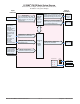
A Conceptual View of the PM
The flexibility of the PM’s software and hardware allows a large range of configurations. Acquiring a better
understanding of the controller’s overall functionality and capabilities while at the same time planning out
how the controller can be used will deliver maximum effectiveness in your application.
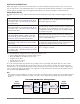
It is useful to think of the controller in three parts: inputs; procedures; and outputs. Information flows
from an input to a procedure to an output when the controller is properly configured. A single PM controller
can carry out several procedures at the same time, for instance closed-loop control, monitoring for several dif-
ferent alarm situations and operating switched devices, such as lights and motors. Each process needs to be
thought out carefully and the controller’s inputs, procedures and outputs set up properly.
Inputs
The inputs provide the information that any given programmed procedure can act upon. In a simple form,
this information may come from an operator pushing a button or as part of a more complex procedure it may
represent a remote set point being received from another controller.
Each analog input typically uses a thermocouple or RTD to read the temperature of something. It can also
read volts, current or resistance, allowing it to use various devices to read humidity, air pressure, operator
inputs and others values. The settings in the Analog Input Menu (Setup Page) for each analog input must be
configured to match the device connected to that input.
Each digital input reads whether a device is active or inactive. A PM with digital input-output hardware
includes two sets of terminals each of which can be used as either an input or an output. Each pair of termi-
nals must be configured to function as either an input or output with the Direction parameter in the Digital
Input/Output Menu (Setup Page).
The Function or EZ Key on the front panel of the PM also operates as a digital input by toggling the func-
tion assigned to it in the Digital Input Function parameter in the Function Key Menu (Setup Page).
Functions
Functions use input signals to calculate a value. A function may be as simple as reading a digital input to set
a state to true or false, or reading a temperature to set an alarm state to on or off. Or, it could compare the
temperature of a process to the set point and calculate the optimal power for a heater.
To set up a function, it’s important to tell it what source, or instance, to use. For example, an alarm may
be set to respond to either analog input 1 or 2 (instance 1 or 2, respectively).
Keep in mind that a function is a user-programmed internal process that does not execute any action outside
of the controller. To have any effect outside of the controller, an output must be configured to respond to a
function.
Outputs
Outputs can perform various functions or actions in response to information provided by a function, such as
operating a heater; turning a light on or off; unlocking a door; or turning on a buzzer.
Assign an output to a Function in the Output Menu or Digital Input/Output Menu. Then select which in-
stance of that function will drive the selected output. For example, you might assign an output to respond to
alarm 4 (instance 4) or to retransmit the value of analog input 2 (instance 2).
You can assign more than one output to respond to a single instance of a function. For example, alarm 2
could be used to trigger a light connected to output 1 and a siren connected to digital output 5.