® OPERATING MANUAL WATER QUALITY & CONDITIONING PRODUCTS WATER CONDITIONER with WM100SM valve
TABLE OF CONTENTS Introduction . . . . . . . . . . . . . . . . . . . . . . . . . . . . . . . . . .1 General Warnings . . . . . . . . . . . . . . . . . . . . . . . . . .1 Principles Of Softening-Ion Exchange . . . . . . . . . .2 Specifications . . . . . . . . . . . . . . . . . . . . . . . . . . . . .5 Quick Reference Specifications . . . . . . . . . . . . . . .5 Service Instructions . . . . . . . . . . . . . . . . . . . . . . . . . . .19 Drive Assembly . . . . . . . . . . . . . . . . . . . . . . . . . .
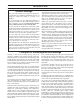
INTRODUCTION General Warnings and establishes the service piston positions. The display should flash all wording, then flash the software version (e.g. 154) and then reset the valve to the service position. All plumbing should be done in accordance with local plumbing codes. The pipe size for the drain line should be a minimum of 1/2". Backwash flow rates in excess of 7 gpm or length in excess of 20' require 3/4" drain line.
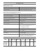
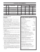
INTRODUCTION Specifications TABLE I Minimum/Maximum Operating Pressures 20 psi (138 kPa) -125 psi (862 kPa) Minimum/Maximum Operating Temperatures 40°F (4°C) -110°F (38°C) Current Draw & Voltage 0.5 Amperes 110 Volts Other options available Table 2 contains a summary of specifications for the control valve and bypass valve. Quick Reference Specifications TABLE 2 Service flowrate (includes bypass) 27 gpm (102.2 lpm) @ 15 psig (103 kPa) drop Backwash flowrate (includes bypass) 27 gpm (102.
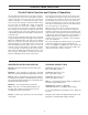
CONTROL VALVE FUNCTIONS Control Valve Function and Cycles of Operation The transformer power pack comes with a 15-foot power cord and is designed for use with the control valve. The transformer power pack is for dry location use only. The control valve remembers all settings for two hours if the power goes out. After two hours the only item that needs to be reset is the time of day, all other values are permanently stored in the nonvolatile memory. The control valve does not need batteries.
INSTALLATION Installation Preview Conduct a visual check of all equipment for any damage that may have occurred during shipment. Note: Softener to be located at least 10 feet away from hot waterheater to protect against hot water back-up. Note: If there is obvious damage to any equipment, it should be noted on the carrier’s Bill Of Lading. Open and inspect the contents of all closed crates, cartons, etc. and inspect for concealed damage. The manufacturer is not liable for any damage during transit.
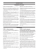
INSTALLATION Figure 2: Plumbing with 3-way b pass. Figure 1: Plumbing with by pass (Standard). Figure 4: 3-way bypass plumbing. Figure 3: Bypass (standard). Figure 6: When installing sweat copper follow state and federal codes by using a lead free solder and flux. Use a joint compound to seal threaded pipe. Some homes use the cold water pipes for an electrical ground (metal only). Whenfinished with plumbing, a ground wire should bre connected to the copper pipes to complete the ground curcuit.
INSTALLATION STEP 3: Move softener into place Note: When assembling the installation fitting package, connect the fitting to the plumbing system first and then attach the nut, split ring and o-ring. Heat from soldering or solvent cements may damage the nut, split ring, and o-ring. Make sure solder joints are cool before assemble is started. Make sure floor is level. Install shims if needed.
INSTALLATION STEP 5: Connect the Drain Line If the drain line is a 5/8" flexible poly tube, slide the nut onto the poly tube, then place the poly tube insert into the end of the poly tube and tighten the nut on to the 3/4" drain line fitting. The nut is only designed for use with flexible poly tube. Use other nuts if attaching different materials. Run line to a drain. Making sure you have a 1 1/2" airgap. You may use a floor drain, standpipe or any open type drain (see Fig 10).
CONTROL PROGRAMMING DIR TIME CLOCK FILTER RESERVE CAPACITY SOFTENER Yes Automatically Calculated Yes Off Auto Yes Yes If desired enter a value less than estimated capacity Yes SETTINGS* REGENERANT BACKWASH ONLY Yes Yes DAY OVERRIDE GALLON CAPACITY Off Auto Off Any Number Any Number Auto Yes Yes Automatically calculated Yes Yes Yes If desired enter a value less than estimated capacity Yes Yes Yes Any Number Any Number Yes None Yes Yes Yes Any Number Off * Day override
CONTROL PROGRAMMING INSTALLER (I) Displays/Settings STEP 1I – Press NEXT and arrow up simultaneously for 3 seconds. STEP 2I – Hardness: Set the amount of hardness in grains of hardness as calcium carbonate per gallon using, arrow down or arrow up buttons. The default is 20 with value ranges from 1 to 150 in 1 grain increments. Note the grains per gallon can be increased if soluble iron needs to be reduced. Press NEXT to go to step 3I. Press REGEN to exit Installer Displays/Settings.
PROGRAMMING (NOTE) SANITIZING THE SYSTEM SET TIME OF DAY 1. At completion of softener installation you should sanitize the system. The user can also set the time of day. Time of day should only need to be set after extended power outages or when daylight savings time begins or ends. If an extended power outage occurs, the time of day will flash on and off which indicates the time of day should be reset. 2. Take the lid off of the salt tank and then take the cap off of the brine well.
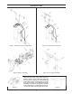
CONTENTS TABLE 10: Injector Order Information PART # COLOR TANK DIA. DRIVE CAP ASSEMBLY Main Piston and Regenerant Piston KC11V3010-1D KC11V3010-1E KC11V3010-1F KC11V3010-1G KC11V3010-1J KC11V3010-1K The drive gears turn the main gear of the drive cap assembly, which moves the piston. The screw-driven, horizontally moving piston stops at specific positions to direct the flow of water to backwash, regenerate, rinse or refill.
CONTENTS The drain line flow control can be installed in the standard 1/4" drain line elbow, which accommodates 5/8" poly tube or 3/4" NPT drain line connections. The optional nut and poly tube insert for the 3/4" drain line elbow is designed for use with flexible poly tube only. The 3/4" drain line elbow can be rotated 180 degrees so the outlet can be orientated to the nearest drain. The same retainer is used for all drain line flow controls for the 3/4" fitting.
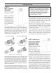
SYSTEM COMPONENTS DESCRIBED Figure 17: Figure 18: Figure 19 Figure 20:: SYSTEM COMPONENTS DESCRIBED Service Instructions DRIVE ASSEMBLY To reassemble seat the bottom of the drive bracket so the notches are engaged at the bottom of the drive back plate. Push the top of the drive bracket towards the two latches. The drive bracket may have to be lifted slightly to let the threaded piston rod pass through the hole in the drive bracket.
SERVICE INSTRUCTIONS board. Move the spring clip loop to the right and hold. Rotate the motor at least a 1/4 turn in either direction before gently pulling on the wire connectors to remove the motor. Pulling directly on the wires without rotating the motor may break the wires off the motor. vinegar or replace the main piston. Reattach the main piston to the drive cap assembly. Reattach the regenerant piston (if needed) to the main piston. Do not lubricate the piston rod, main piston or regenerant piston.
CONTENTS The plug and/or injector can be pried out with a small screwdriver. The plug can be wiped clean. If the plug leaks replace the entire plug. The injector consists of a throat and a nozzle. Chemically clean the injector with vinegar or sodium bisulfite. The holes can be blown out with air. Both pieces have small diameter holes that control the flow rates of water to insure that the proper concentration of regenerant is used.
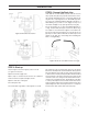
DRAWING AND PART NUMBERS BRINE TANK AND SOFTENER TANK Figure 17 Figure 18 FRONT COVER AND DRIVE ASSEMBLY Drawing No. Order No. Description Qty.
CONTENTS DRIVE CAP ASSEMBLY, DOWNFLOW PISTON, UPFLOW PISTON, REGENERANT PISTON AND SPACER STACK ASSEMBLY Drawing No. 1 2 3 4 5 6 Order No. Description KC12V3005 W100SM Spacer Stack Assembly KC12V3004 Drive Cap ASY KC12V3135 O-ring 228 KC12V3011 W100SM Piston Downflow ASY KC12V3174 W100SM Regenerant Piston KC12V3180 O-ring 337 Qty. 1 1 1 1 3 1 Note: The regenerant piston is not used in backwash only applications. INJECTOR CAP, INJECTOR SCREEN, INJECTOR, PLUG AND O-RING Drawing No.
DRAWING AND PART NUMBERS Drawing No. 1 2 3 4 5 6 7 8 Order No. Description KC12V3195-01 KC12H4615 KC12JCP-P-6 KC12JCPG-6PBLK KC12H4613 KC12V3163 KC12V3165-01 KC12V3182 Qty. W100SM Refill Port Plug ASY Elbow Locking Clip Polytube insert 3/8 Nut 3/8 Elbow Cap 3/8 O-ring 019 W100SM RFC Retainer ASY W100SM RFC ** 1 1 1 1 1 1 1 *Assembly includes WS1 RFC. **This part is required for backwash only systems. DRAIN LINE - 3/4" Drawing No. Order No.
DRAWING AND PART NUMBERS WATER METER AND METER PLUG Drawing No. Order No. 1 2 3 4 5 KC12V3151 KC12V3003 KC12V3118-01 KC12V3105 KC12V3003-01 Description Qty. W100SM Nut 1” QC W100SM Meter ASY W100SM Turbine ASY O-ring 215 W100SM Meter Plug ASY 1 1 1 1 1 * Order number KC12V3003 includes KC12V3118-01 and KC12V3105. INSTALLATION FITTING ASSEMBLIES Drawing No. Order No.
DRAWING AND PART NUMBERS BYPASS VALVE Drawing No. Order No. 1 2 3 4 5 6 7 8 9 10 KC12V3151 KC12V3150 KC12V3105 KC12V3145 KC12V3146 KC12V3147 KC12V3148 KC12V3152 KC12V3155 KC12V3156 Description W100SM Nut 1” Quick Connect W100SM Split Ring O-ring 215 W100SM Bypass 1” Rotor W100SM Bypass Cap W100SM Bypass Handle W100SM Bypass Rotor Seal Retainer O-ring 135 O-ring 112 O-ring 214 Qty. 2 2 2 2 2 2 2 2 2 2 (Not Shown) Order No.KC12 V3191-01. Description: WS100sm Bypass Vertical Adapter Assembly. Order No.
DRAWING AND PART NUMBERS flow diagram...service flow diagram...rinse flow diagram...backwash flow diagram...fill flow diagram...
TROUBLESHOOTING System Troubleshooting PROBLEM CAUSE CORRECTION 1. Loss of Resin A. Broken distribution tube A. Replace distribution tube. B. Inlet/Outlet connection reversed. B. Reconnect inlet/outlet connection properly. A. Electrical service to unit has been interrupted. A. Assure permanent electrical service (check fuse, plug, pull chain or switch. B. Timer is defective. B. Replace timer. C. Power failure. C. Reset time of day. A. Bypass valve is open. A. Close bypass valve. B.
TROUBLESHOOTING System Troubleshooting (continued) PROBLEM CAUSE CORRECTION 8. Excessive water in brine tank. A. Plugged drain line flow control. A. Clean flow control. B. Plugged injector system. B. Clean injector and screen. C. Foreign material in brine valve. C.. Replace timer. D. Defectie controller. D. Replace controller. E. Foreign material in brine line flow control. E. Clean brine line flow control. A. Drain line flow control is plugged. A. Clean drain line flow control B.
TROUBLESHOOTING Troubleshooting Programming PROBLEM POSSIBLE CAUSE SOLUTION 1. Timer does not display time of day a. Transformer unplugged a. Connect power b. No electric power at outlet b. Repair outlet or use working outlet. c. Defective transformer c. Replace transformer d. Defective PC board d. Replace PC board a. Switched outlet a. Use uninterrupted outlet b. Power outage b. Reset time of day c. Defective PC board c. Replace PC board a. Bypass valve in bypass position a.
CONTENTS Troubleshooting Programming (continued) PROBLEM POSSIBLE CAUSE SOLUTION 6. Control valve stalled in regeneration a. Motor not operating a. Replace motor b. No electric power at outlet b. Repair outlet or use working outlet c. Defective transformer c. Replace transformer d. Defective PC board d. Replace PC board e. Broken drive gear or drive cap assembly e. Replace drive gear or drive cap assembly f. Broken piston retainer f. Replace drive cap assembly g.
DISTRIBUTED BY: Manufactured by Watts Water Quality & Conditioning Products, 13700 Highway 90 W.