
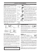
Specifications


13
CONTENTS
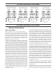
DRIVE CAP ASSEMBLY
Main Piston and Regenerant Piston
The drive gears turn the main gear of the drive cap assembly,
which moves the piston. The screw-driven, horizontally mov-
ing piston stops at specific positions to direct the flow of water
to backwash, regenerate, rinse or refill. The PC board deter-
mines the position of the piston by counting pulses produced
when the piston is moved. An optical sensor looking at one of
the reduction drive gears generates these pulses. Each cycle
position is defined by a number of pulses. The counter is
zeroed each time the valve goes to the service position. The
PC board finds the service position by noting the increase in
current delivered to the motor when the mechanical stop at
the service position is reached. This method of controlling pis-
ton position allows for greater flexibility and requires no
switches or cam
s.
One of two main pistons is always used:
1. The down flow piston which is used when the control
valve is used as a down flow softener, regenerating
filter or nonregenerating filter: or
2. The up flow piston, which is used when the control valve
is used as an up flow softener.
If the control valve is used as a softener or a regenerating
filter, a regenerant piston must be attached to the main piston.
If the control valve is to be used on system that does not
require a regenerant to be added the regenerant piston must
be removed.
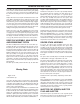
SPACER STACK ASSEMBLY
The spacer stack assembly provides the necessary flow pas-
sage for water during the different cycles.The all-plastic spac-
er stack assembly (patent pending) is a one-piece design,
which allows the stack to be removed using your fingers.
The exterior of the stack is sealed against the body bore with
self-lubricating EPDM o-rings while the interior surface is
sealed against the piston using slippery self cleaning direc-
tional (oneway) silicone lip seals. The lip seals are red or clear
in color and have a special slippery coating so that the piston
does not need to be coated or lubricated.
INJECTOR
T
he screen, injector and/or injector plug(s) are installed under
the injector cap in an easy to access location on top of the valve.
The injector cap contains four slots so no water accumulates
in the cap. The injector cap is designed to be hand tightened.
Under the injector cap there is an easy to clean removable
screen to prevent fouling of the injector. There are two holes
under the injector cap labeled “DN” and “UP”. The holes will be
filled with a plug or an injector.
The plug (#KC113010-IZ) prevents water from traveling through
the pathway. The injector lets water pass through the pathway.
The self-priming injector increases the velocity of the water, cre-
ating a zone of negative pressure that draws in the concentrated
liquid regenerant, such as sodium chloride (brine), potassium
permanganate, sodium hydroxide, hydrochloric acid, etc. The
regenerant blends with the stream of water, which passes
through the media to regenerate the bed.
The injector provides a consistent regenerant/water mixture ratio
over the entire operating pressure range of the control valve. The
injector provides good performance in a variety of applications,
which may involve elevated drain lines and long regenerant draw
lenghts. Injectors are chosen by knowing the type, amount, and
regenerant flow rate for a particular type of media. The color-
coded injectors give different regenerant draw, slow rinse and total
flow rates over the pressure range. See Table 10 for color codes.
REFILL FLOW CONTROL Assembly
The refill flow control assembly consists of a refill flow elbow, refill
flow control retainer assembly, refill flow control, poly tube insert
and nut assembly. The refill flow control retainer fits in the refill
elbow. The refill flow control retainer houses the refill flow control,
which controls the flow rate when the regenerant tank is being
refilled. The refill flow control is a flexible washer-like part with a
small orifice and a precision molded contour that delivers a
steady 0.5 gpm regenerant tank refill rate at varying inlet
pressures. Refill is accomplished with treated water.
The refill flow control assembly is installed in an easy to access
refill elbow located on top of the control valve. The refill flow con-
trol assembly is attached to the control valve with a locking clip.
The locking clip allows the elbow to rotate 270 degrees so the
outlet can be orientated towards the regenerant tank.
DRAIN LINE FLOW CONTROL/Fitting
The drain line flow control assembly includes a drain line flow
control and a fitting. The drain line flow control allows proper
media bed expansion by regulating the flow rate to the drain.
The drain line flow control is a flexible washer-like part with an
orifice and a precision molded contour. The flow rates are
within +- 10% over the pressure range of 1-0 psi to 125 psi.
The flexible washer-like parts are identified with three num-
bers, which correspond to the flow rate in gallons per minute.
See Table 11.
The drain line flow control and fitting are located on top of the
control valve and replaceable without the use of special tools.
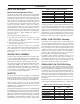
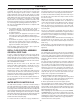
TABLE 10: Injector Order Information
PART # COLOR TANK DIA.
KC11V3010-1D RED 9"
KC11V3010-1E WHITE 10"
KC11V3010-1F BLUE 12"
KC11V3010-1G YELLOW 13"
KC11V3010-1J LT BLUE 16"
KC11V3010-1K LT GREEN 21"
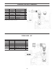
TABLE 11: Drain Line Flow Control (3/4" Fitting)
PART # Number on Backwash Flow Rate
Fitting GPM
KC11V3162-022 22 2.2
KC11V3162-027 27 2.7
KC11V3162-03 32 3.2
KC11V3162-053 53 5.3
KC11V3162-075 75 7.5
KC11V3190-110 110 11